Looking to install a 120V Intermatic timer but not sure how to wire it up? You’ve come to the right place! In this article, we’ll walk you through the process step by step, making it easy for you to get your timer up and running in no time.
Before we dive into the wiring diagram, let’s first understand the basics of how a 120V Intermatic timer works. These timers are commonly used for controlling outdoor lighting, pool pumps, and other electric devices. They allow you to set specific times for your devices to turn on and off, helping you save energy and automate your home.

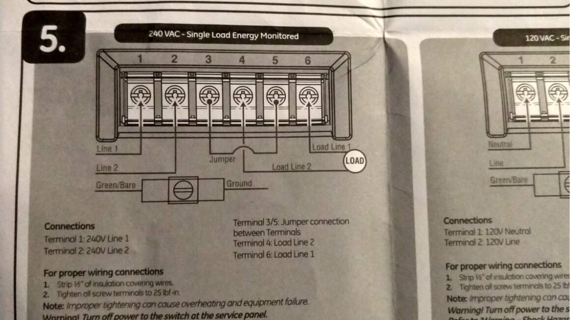
120V Intermatic Timer Wiring Diagram
120V Intermatic Timer Wiring Diagram
Now, let’s get into the nitty-gritty of wiring your 120V Intermatic timer. First, make sure to turn off the power to the circuit you’ll be working on to avoid any accidents. Then, follow the wiring diagram provided by Intermatic, which typically includes connections for power, load, and ground.
Start by connecting the power wire from your electrical panel to the power terminal on the timer. Next, connect the load wire from the device you want to control to the load terminal on the timer. Finally, connect the ground wire to the ground terminal on the timer to ensure safe operation.
Once you’ve made all the necessary connections, double-check your work to ensure everything is secure and properly connected. Then, restore power to the circuit and test your timer to make sure it’s working correctly. If everything checks out, you’re all set!
Remember, if you’re ever unsure about any part of the installation process, don’t hesitate to consult a professional electrician for assistance. It’s always better to be safe than sorry when it comes to working with electricity.
With this simple guide, you should now have a good understanding of how to wire a 120V Intermatic timer. By following these steps and taking proper safety precautions, you can easily install your timer and enjoy the convenience and energy savings it provides. Happy wiring!
Download and Print 120V Intermatic Timer Wiring Diagram Listed below

Main 24 Hour 2 Circuit Electronic Control 120 277 VAC 60 Hz 2

Electrical Identifying Wires In An Intermatic Pool Pump Timer

Amazon Intermatic Sprinkler Irrigation Timer T8845PV With 14

Need Help Wiring New Intermatic Timer The Old One Bit The Dust

Electrical Identifying Wires In An Intermatic Pool Pump Timer


