If you’re looking to upgrade or repair your 24V electric scooter controller, having a wiring diagram is essential. Understanding how the controller is wired can help you troubleshoot any issues and make modifications with ease.
In this article, we will provide you with a detailed 24V electric scooter controller wiring diagram. Whether you’re a beginner or an experienced DIY enthusiast, this guide will help you navigate the wiring process smoothly.

Related Post John Deere 111 Moo111S242340 Wiring Diagram Manual
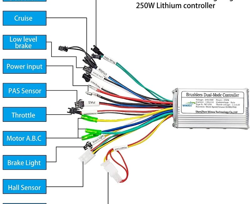
Next, locate the wiring harness that connects all the components to the controller. This harness typically consists of colored wires that correspond to specific functions such as power, ground, throttle input, brake input, and motor output. Make sure to carefully inspect each wire for any signs of damage or wear.
Refer to the wiring diagram provided by the manufacturer of your 24V electric scooter controller. This diagram will illustrate the correct placement of each wire and connector. It’s essential to follow the diagram precisely to avoid any wiring errors that could potentially damage your controller or other components.
Once you have identified the correct wiring configuration, begin connecting each wire to its designated terminal on the controller. Take your time and double-check each connection to ensure everything is properly secured. Once all the wires are connected, power up your electric scooter and test the functionality of the controller.
In conclusion, having a clear understanding of the wiring diagram for your 24V electric scooter controller is essential for maintaining and customizing your ride. By following the steps outlined in this guide, you can confidently wire your controller and enjoy a smooth and efficient riding experience.
Download and Print 24V Electric Scooter Controller Wiring Diagram Listed below