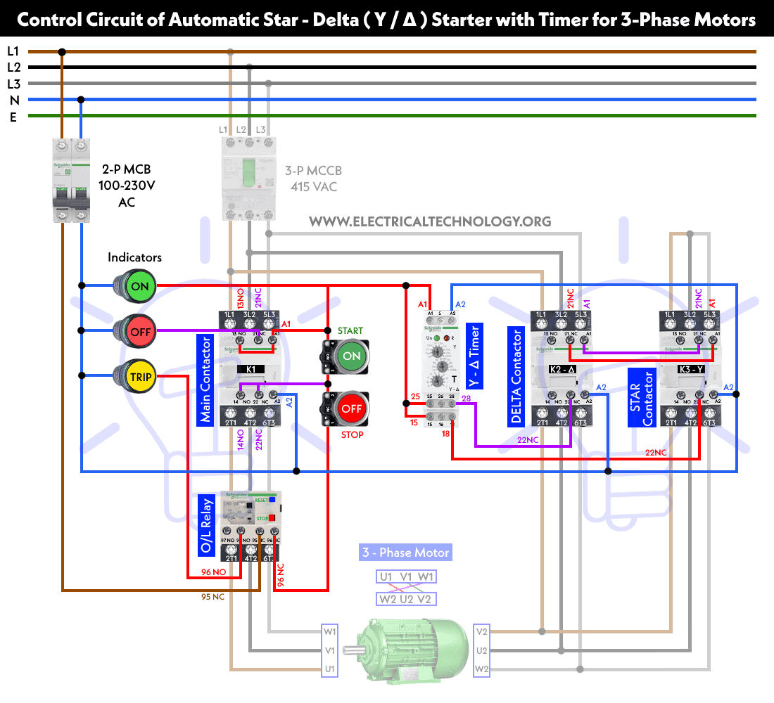
When it comes to electrical wiring, understanding how to properly wire a 3 phase contactor for start and stop operation is crucial. This type of wiring diagram is commonly used in industrial settings to control motors and other equipment.
By following a 3 phase contactor wiring diagram for start stop operation, you can ensure that your equipment operates safely and efficiently. Whether you’re a seasoned electrician or a DIY enthusiast, knowing how to wire a contactor is a valuable skill to have.
Related Post Gm Ignition Switch Wiring Diagram
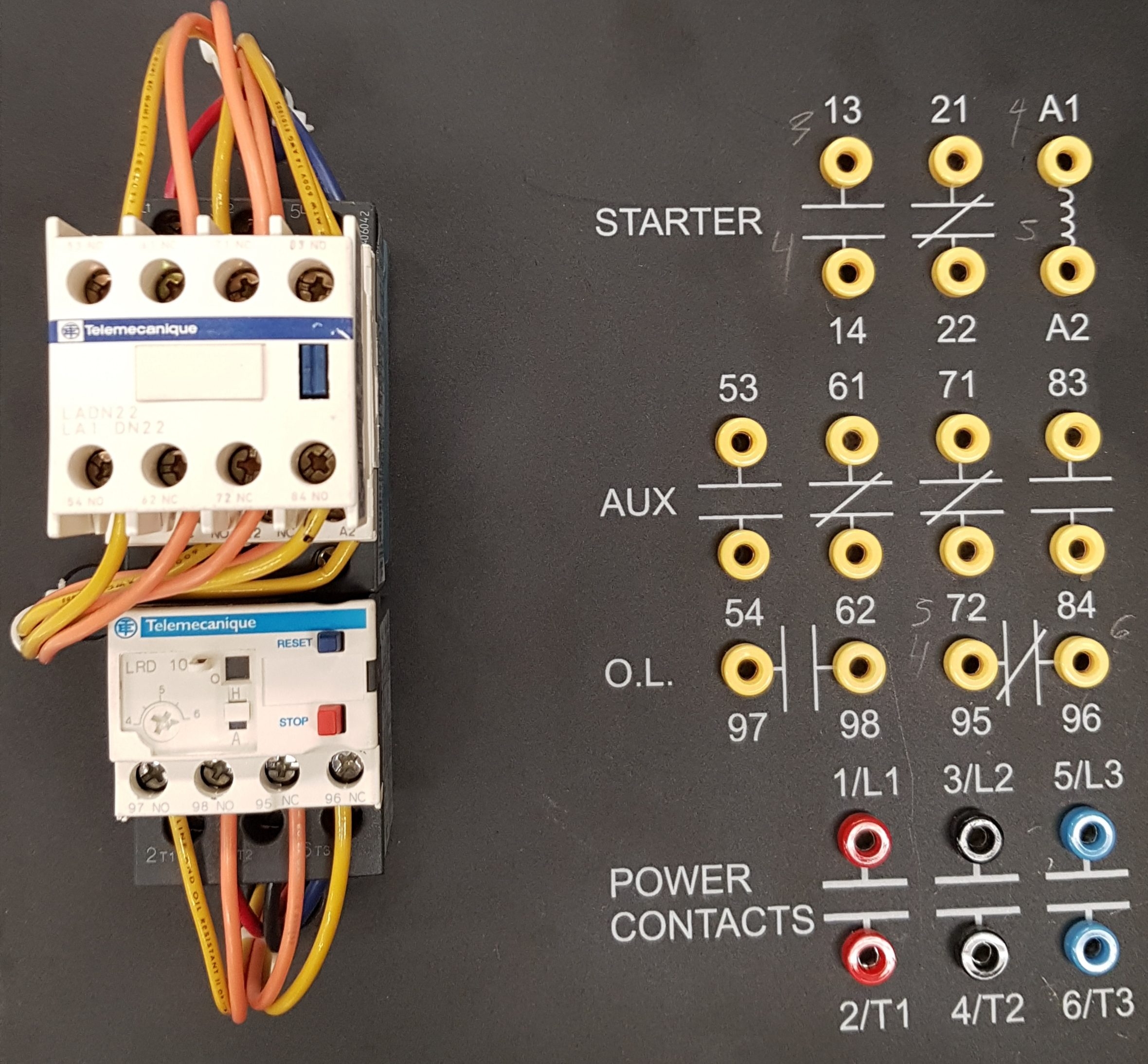
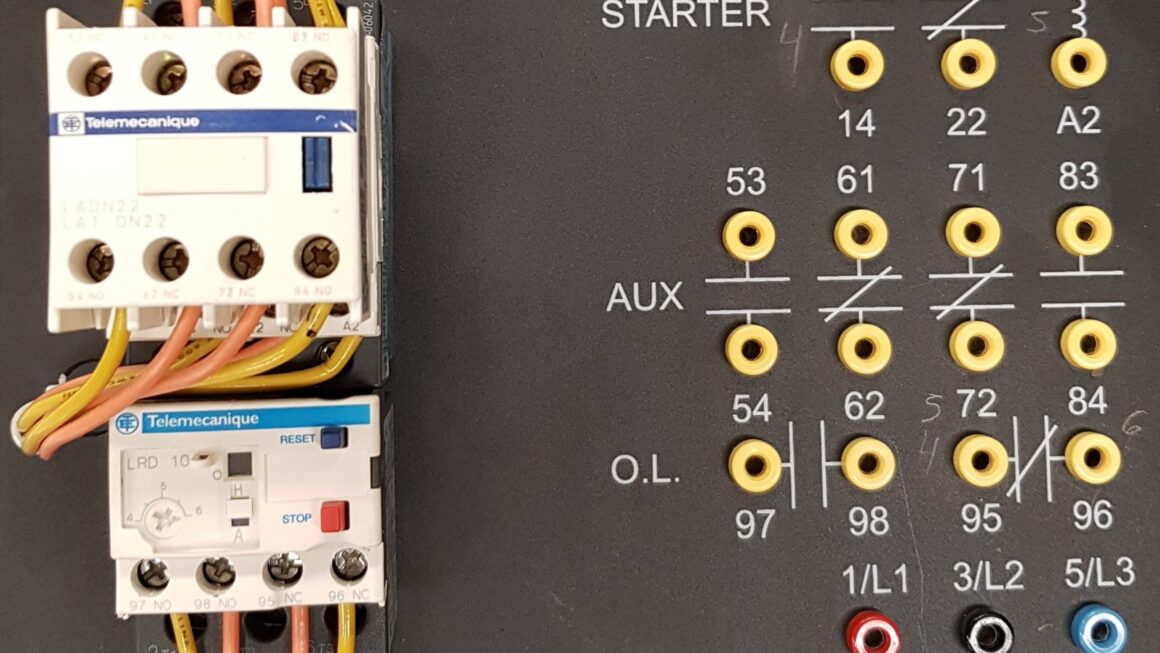
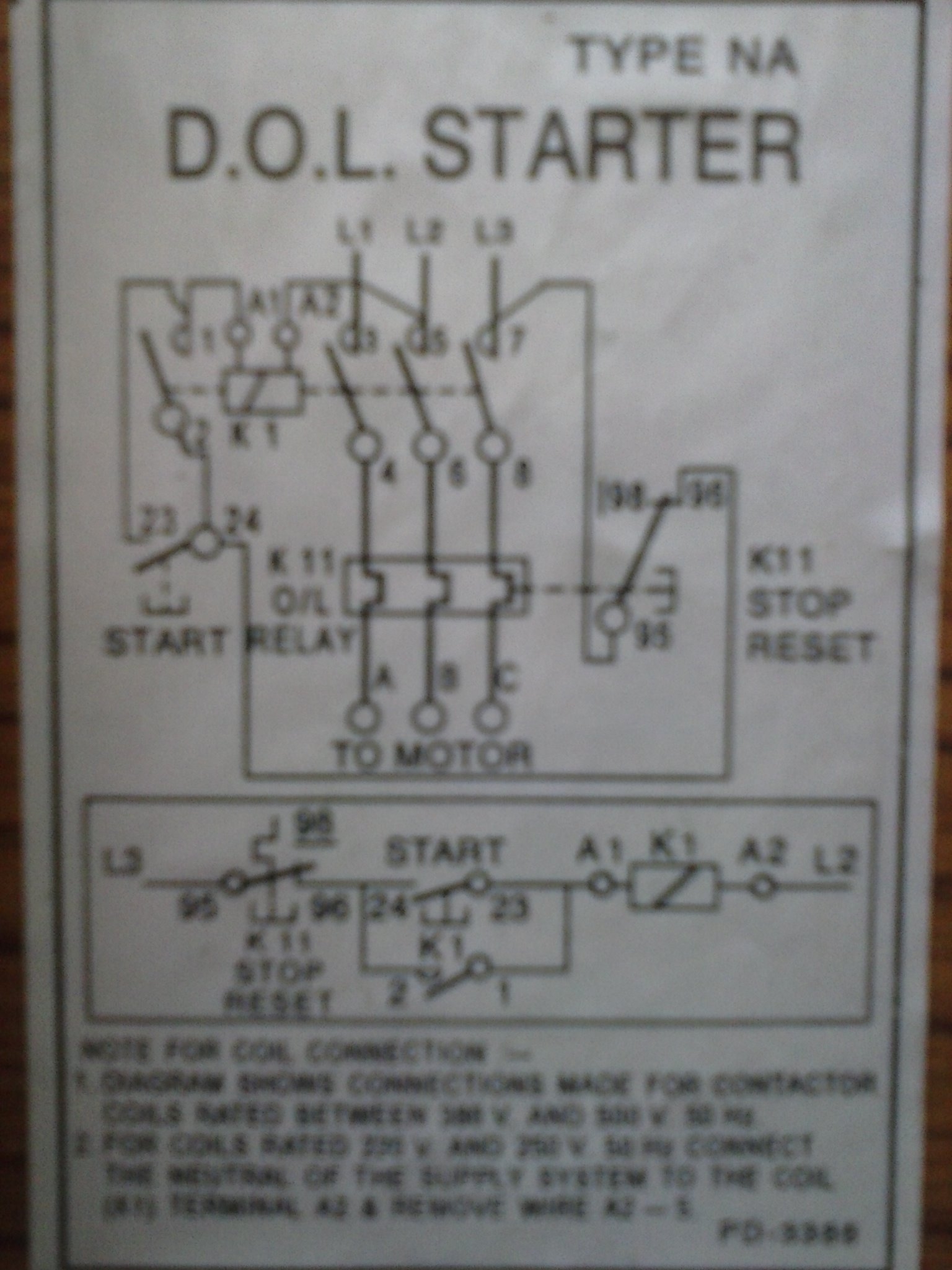
To wire a 3 phase contactor for start stop operation, you’ll need to connect the power supply, motor, and control circuit according to the wiring diagram. This diagram will show you how to properly connect the incoming power, control circuit, and motor leads to the contactor.
Once you have all the connections in place, you can test the operation of the contactor by energizing the control circuit. When the start button is pressed, the contactor should close and power the motor. When the stop button is pressed, the contactor should open and de-energize the motor.
Remember to always follow safety precautions when working with electrical wiring. Make sure to turn off the power supply before making any connections and double-check your wiring before energizing the circuit. By following a 3 phase contactor wiring diagram for start stop operation, you can ensure the safety and efficiency of your electrical system.
In conclusion, understanding how to wire a 3 phase contactor for start stop operation is essential for anyone working with industrial equipment. By following a wiring diagram and taking proper safety precautions, you can ensure that your equipment operates smoothly and safely. So, next time you need to wire a contactor, refer to a reliable diagram and get the job done right!
Download and Print 3 Phase Contactor Wiring Diagram Start Stop Pdf Listed below
