If you’re looking to install a new ignition switch in your vehicle, understanding the wiring diagram is crucial. A 4 wire ignition switch wiring diagram can help you navigate the process with ease.
When it comes to wiring your ignition switch, having a clear diagram can save you time and frustration. By following the guidelines laid out in the diagram, you can ensure a smooth installation process.

Related Post Low Voltage Landscape Lighting Wiring Diagram
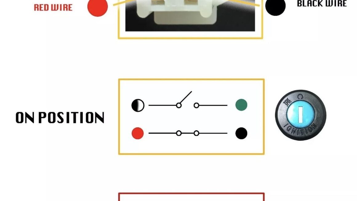
Start by identifying each wire and its corresponding terminal on the ignition switch. The battery wire is usually connected to the terminal marked “B,” while the ignition wire goes to the “I” terminal. The starter wire is linked to the “S” terminal, and the accessory wire connects to the “A” terminal.
Once you have identified the wires and their terminals, carefully connect each one according to the diagram. Double-check your connections to ensure they are secure and accurate before testing the ignition switch. Following the diagram precisely will help prevent any wiring errors that could cause issues down the line.
By using a 4 wire ignition switch wiring diagram as a guide, you can confidently install your new ignition switch with ease. Taking the time to understand the wiring layout will ensure a successful installation and reliable performance from your vehicle’s ignition system.
With the help of a clear and concise wiring diagram, you can tackle the task of installing a 4 wire ignition switch with confidence. By following the diagram’s instructions and double-checking your connections, you’ll be on your way to a smoothly functioning ignition system in no time.
Download and Print 4 Wire Ignition Switch Wiring Diagram Listed below