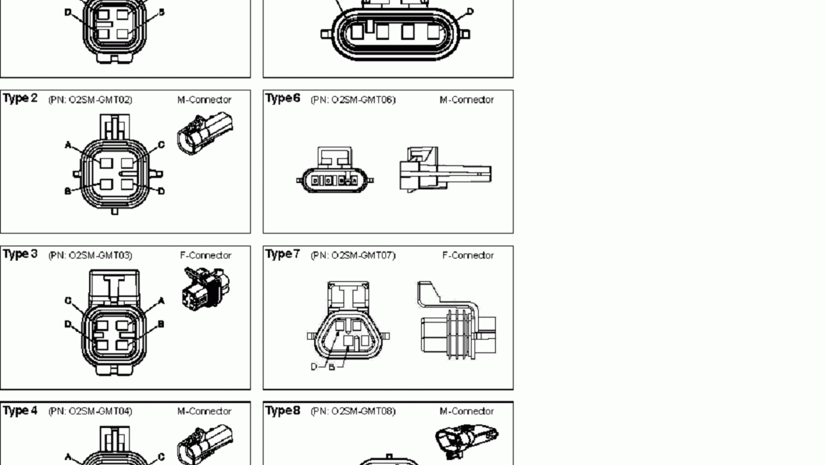
If you’re looking to understand how a 4 wire lambda sensor works, you’ve come to the right place. In this article, we’ll break down the wiring diagram for a 4 wire lambda sensor and explain how it functions.
A 4 wire lambda sensor, also known as an oxygen sensor, is a crucial component in your vehicle’s exhaust system. It helps monitor the air-fuel ratio in the engine to ensure optimal performance and fuel efficiency.
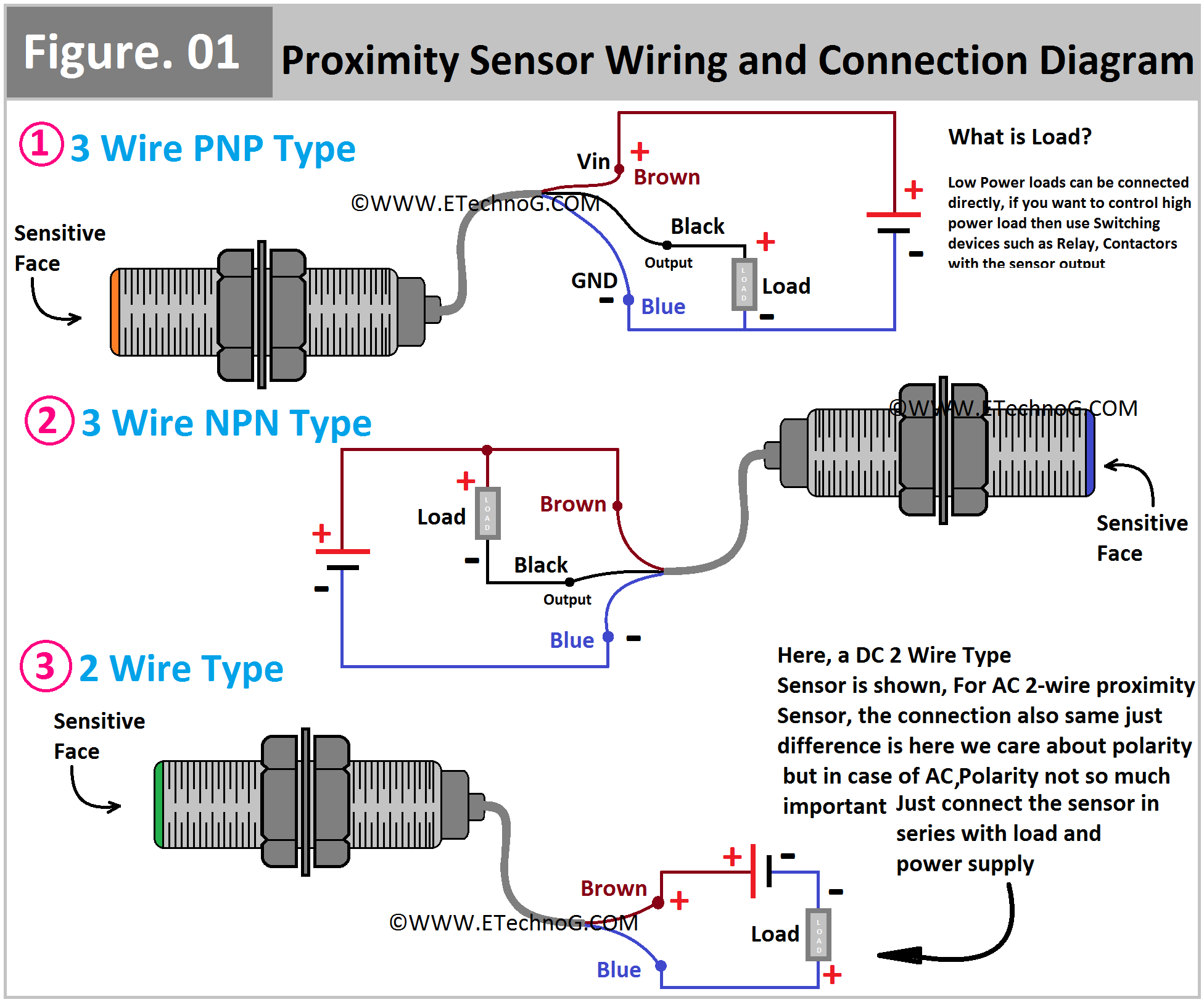
Related Post Wiring A 3 Way Light Switch Diagram
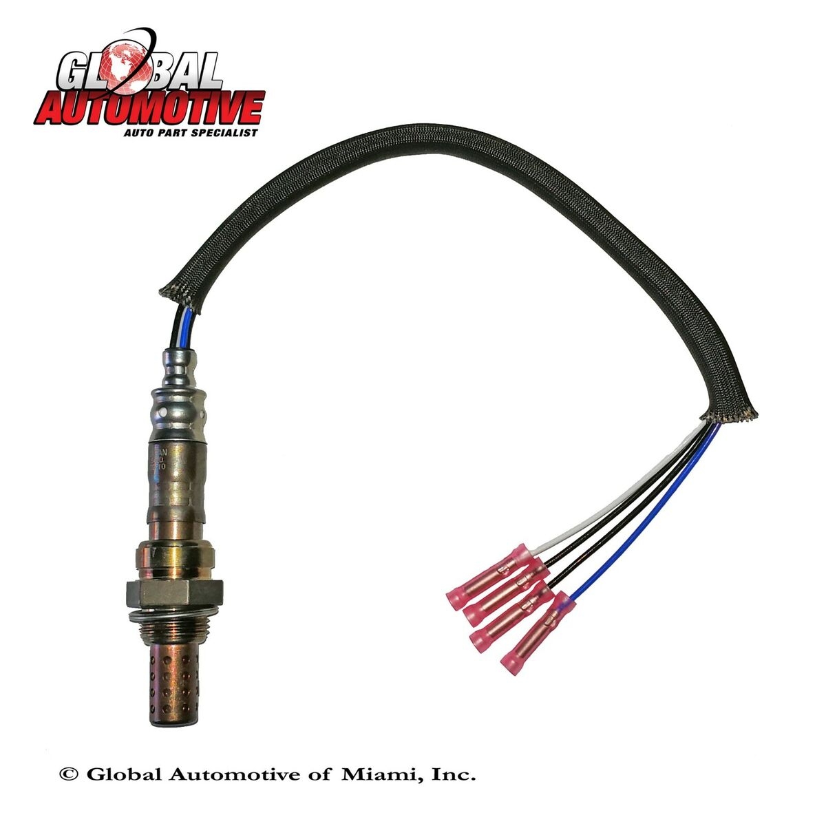
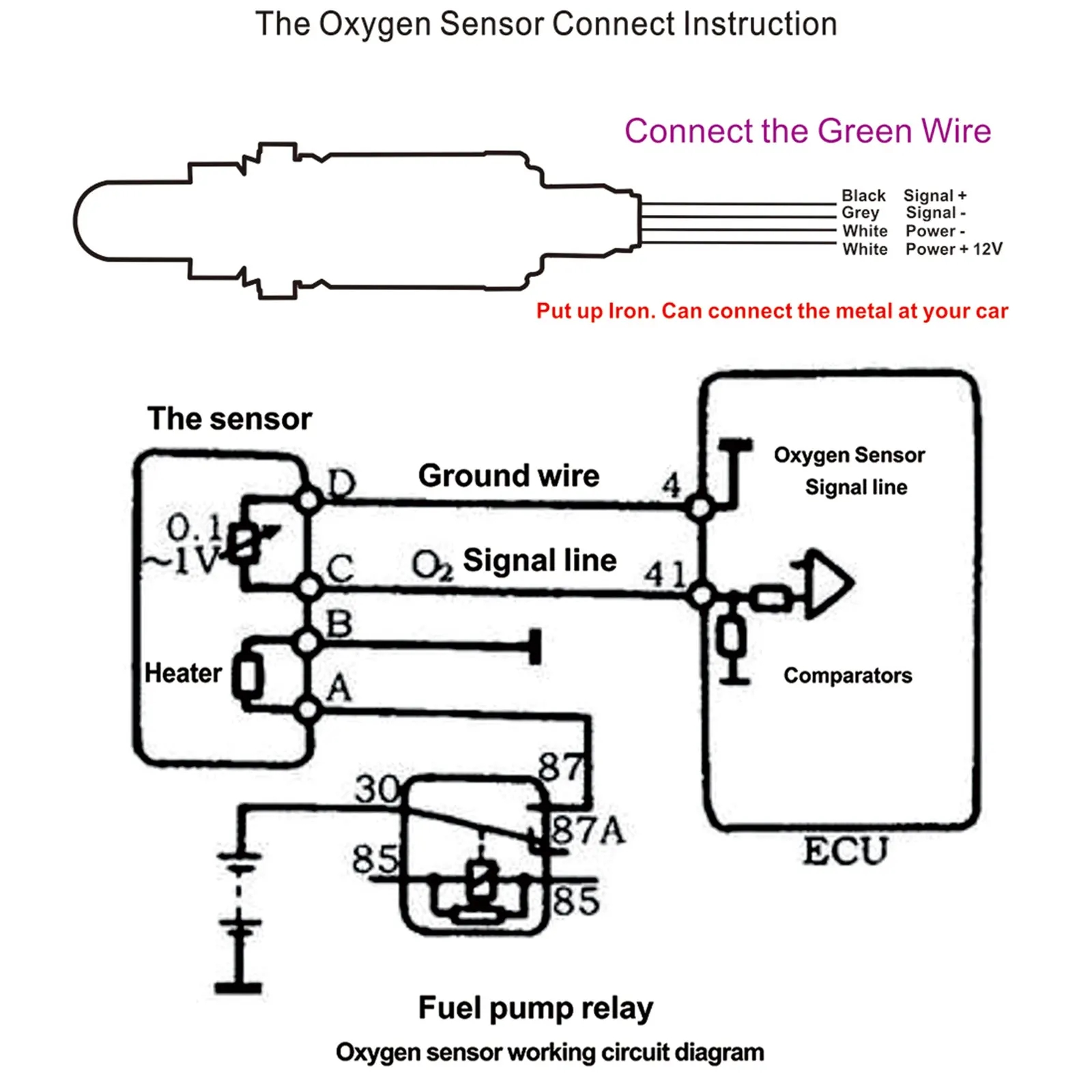
The two black wires are for the sensor’s heater circuit, which helps the sensor reach its operating temperature quickly. The white wire is for the sensor signal, which sends information about the air-fuel ratio to the engine control unit. Lastly, the gray wire is the sensor ground, providing a reference point for the sensor’s operation.
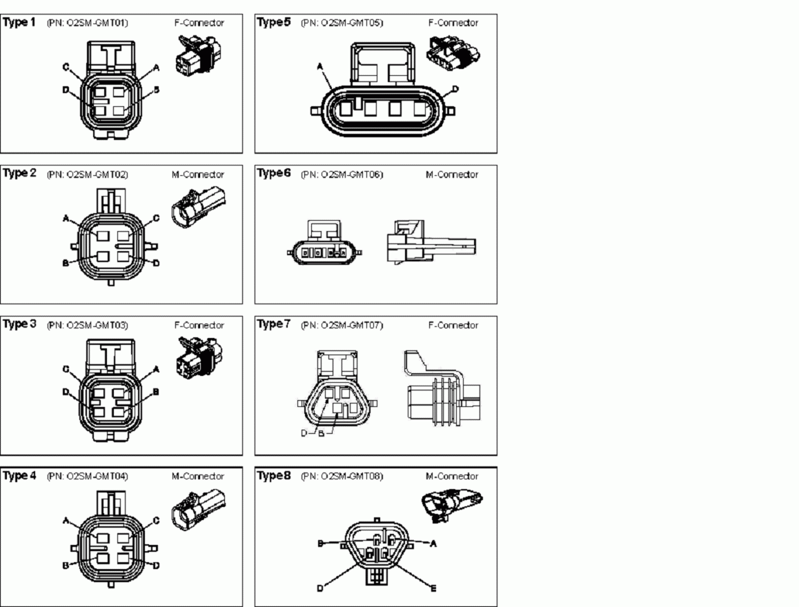
When wiring a 4 wire lambda sensor, it’s essential to follow the manufacturer’s instructions carefully. Make sure to connect each wire to the correct terminal to ensure proper sensor function. Improper wiring can lead to engine performance issues and decreased fuel efficiency.
In conclusion, understanding the wiring diagram for a 4 wire lambda sensor is crucial for maintaining your vehicle’s performance. By following the correct wiring procedures, you can ensure that your sensor operates efficiently and helps your engine run smoothly.
Hopefully, this article has helped shed some light on the 4 wire lambda sensor wiring diagram. Remember to consult your vehicle’s manual or a professional mechanic if you have any doubts about wiring the sensor correctly. Keep your vehicle running smoothly and efficiently with the right knowledge and care!
Download and Print 4 Wire Lambda Sensor Wiring Diagram Listed below
