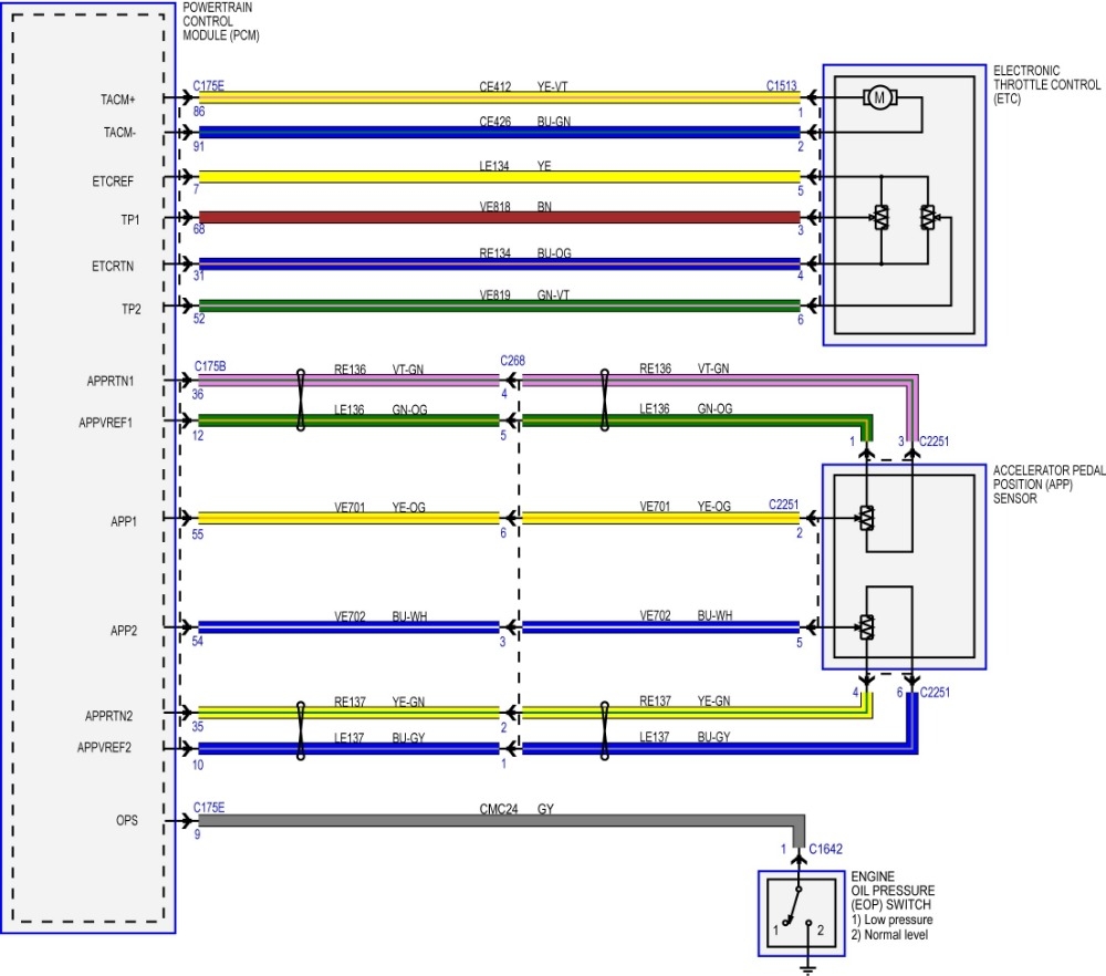
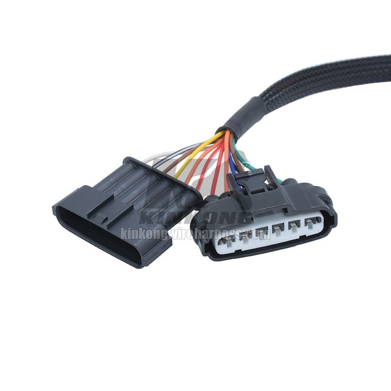
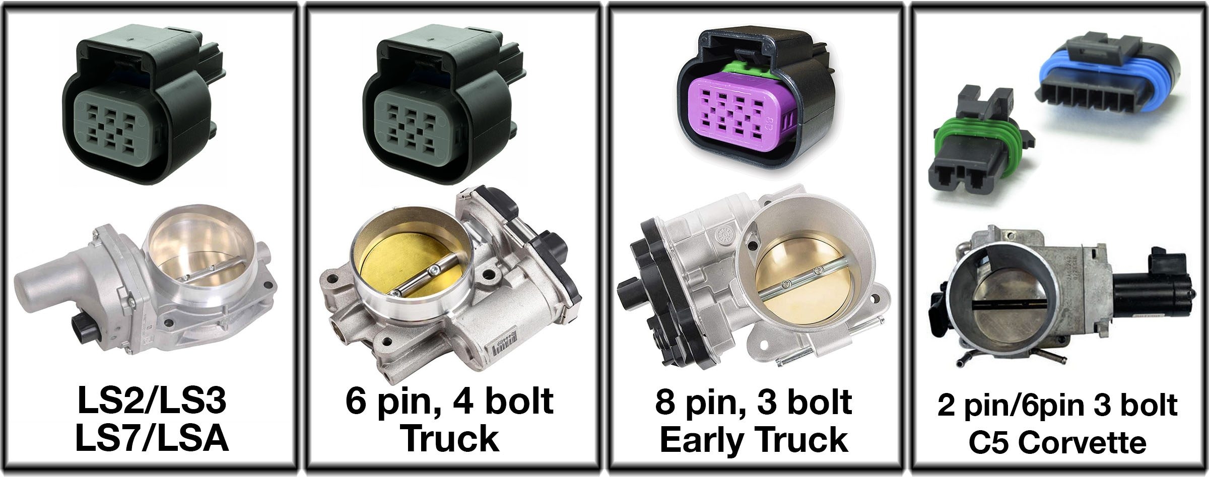
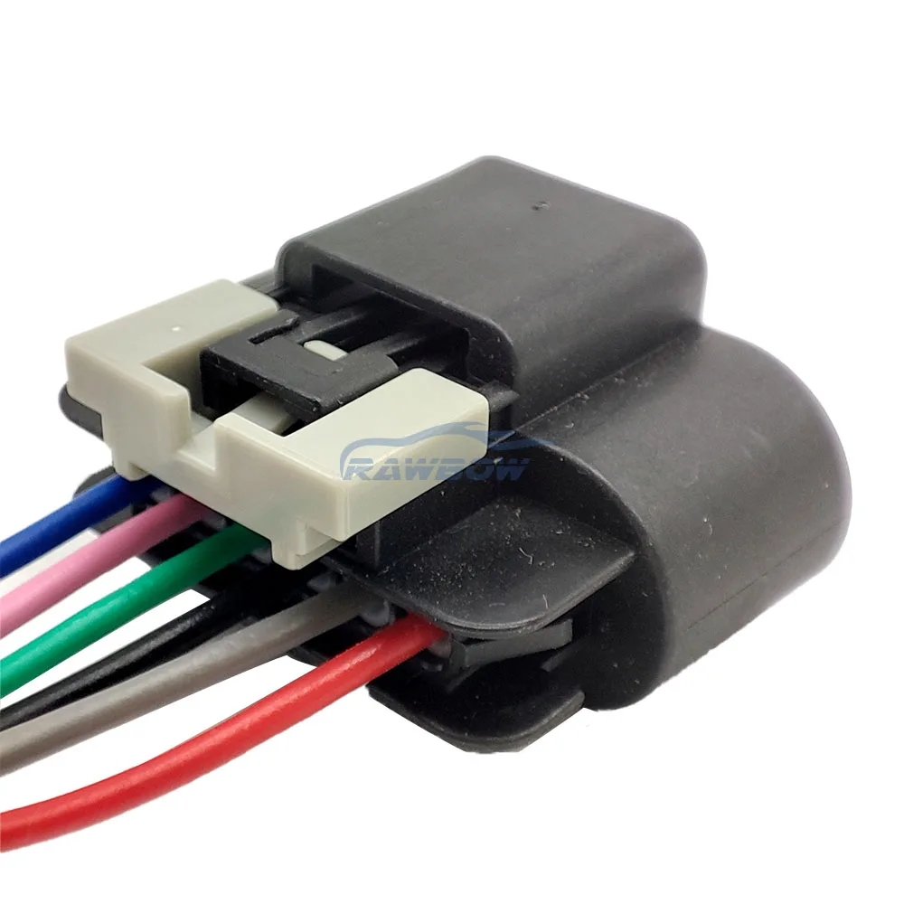
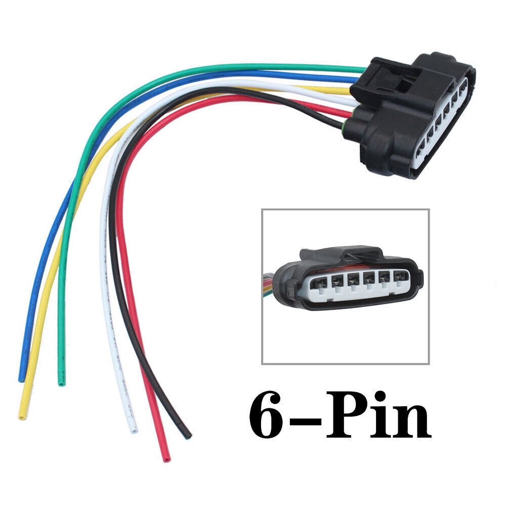
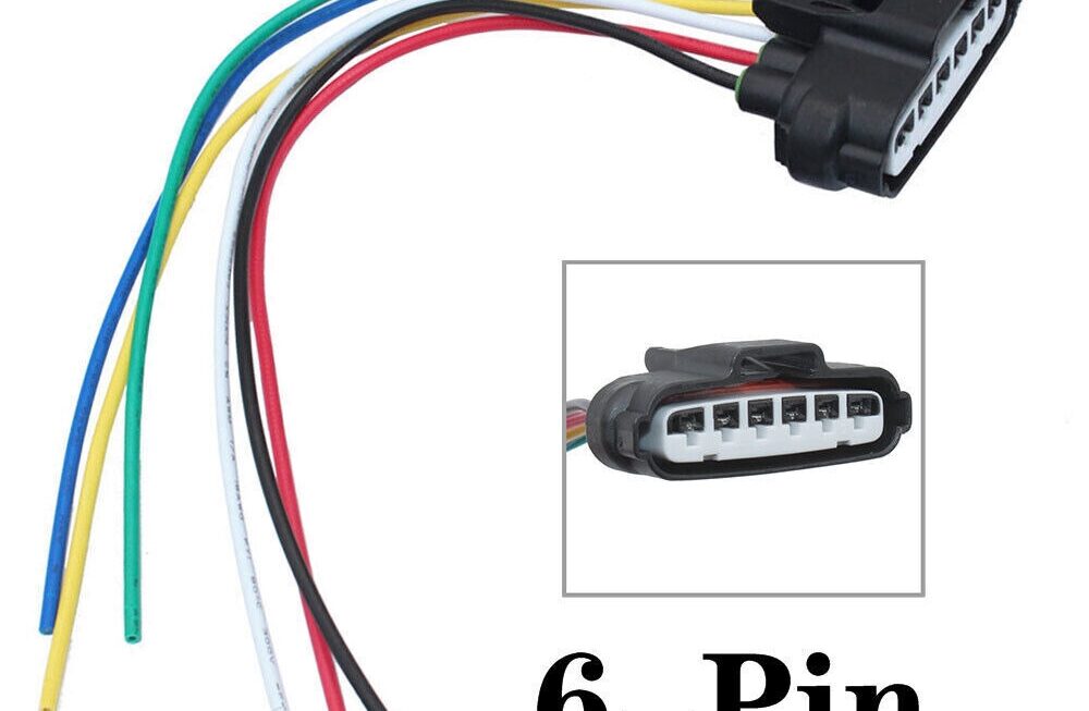
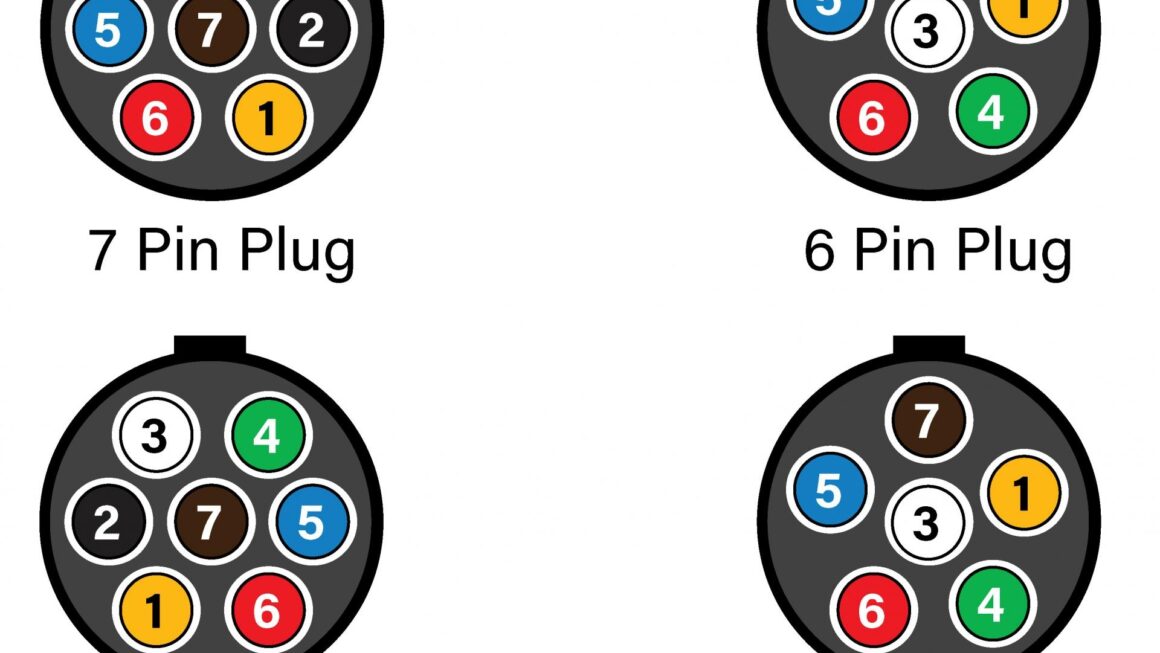
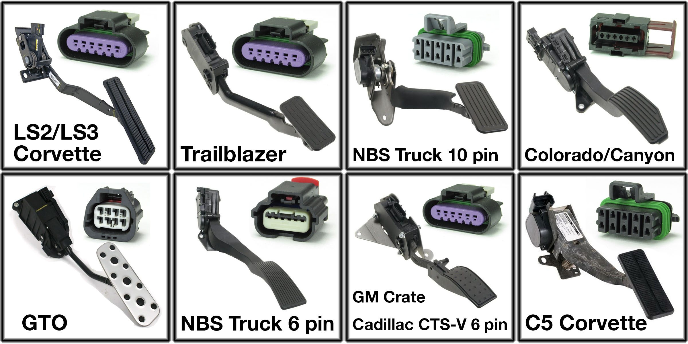
Are you looking for a simple and easy-to-understand 6 Pin Throttle Position Sensor Wiring Diagram? Look no further! In this article, we will break down the wiring diagram for a 6 pin throttle position sensor in a way that is easy to follow and implement.
Whether you are a beginner or an experienced DIYer, understanding the wiring diagram for a throttle position sensor is crucial for proper installation and troubleshooting. By following our guide, you will be able to confidently wire up your 6 pin throttle position sensor without any confusion.
Related Post 480 To 208 Transformer Wiring Diagram
Next, start by connecting the Vref pin to a 5V power source, the Ground pin to a suitable ground connection, and the Signal pin to your engine control unit. These three connections are essential for the proper functioning of your throttle position sensor.
Additionally, you will need to wire the Heater Ground, Heater Power, and Heater Control pins if your sensor is equipped with a heater element. This will ensure that your sensor operates efficiently in all weather conditions.
Once you have connected all six pins according to the wiring diagram, double-check your connections to ensure everything is secure and properly insulated. Finally, test your throttle position sensor to verify that it is functioning correctly before putting everything back together.
In conclusion, understanding and implementing a 6 Pin Throttle Position Sensor Wiring Diagram is essential for the proper functioning of your vehicle’s engine control system. By following our simple and easy-to-follow guide, you will be able to wire up your sensor with confidence and precision. Happy wiring!
Download and Print 6 Pin Throttle Position Sensor Wiring Diagram Listed below
