Have you ever wondered how a 90-113 boiler wiring diagram works? In this article, we will explore the ins and outs of this important piece of equipment.
Boilers are essential for heating water and providing warmth in homes and buildings. The wiring diagram is like a roadmap that guides the electrical connections within the boiler to ensure it functions properly.

Related Post Wiring Diagram Kawasaki Bayou 220
Understanding the 90-113 Boiler Wiring Diagram
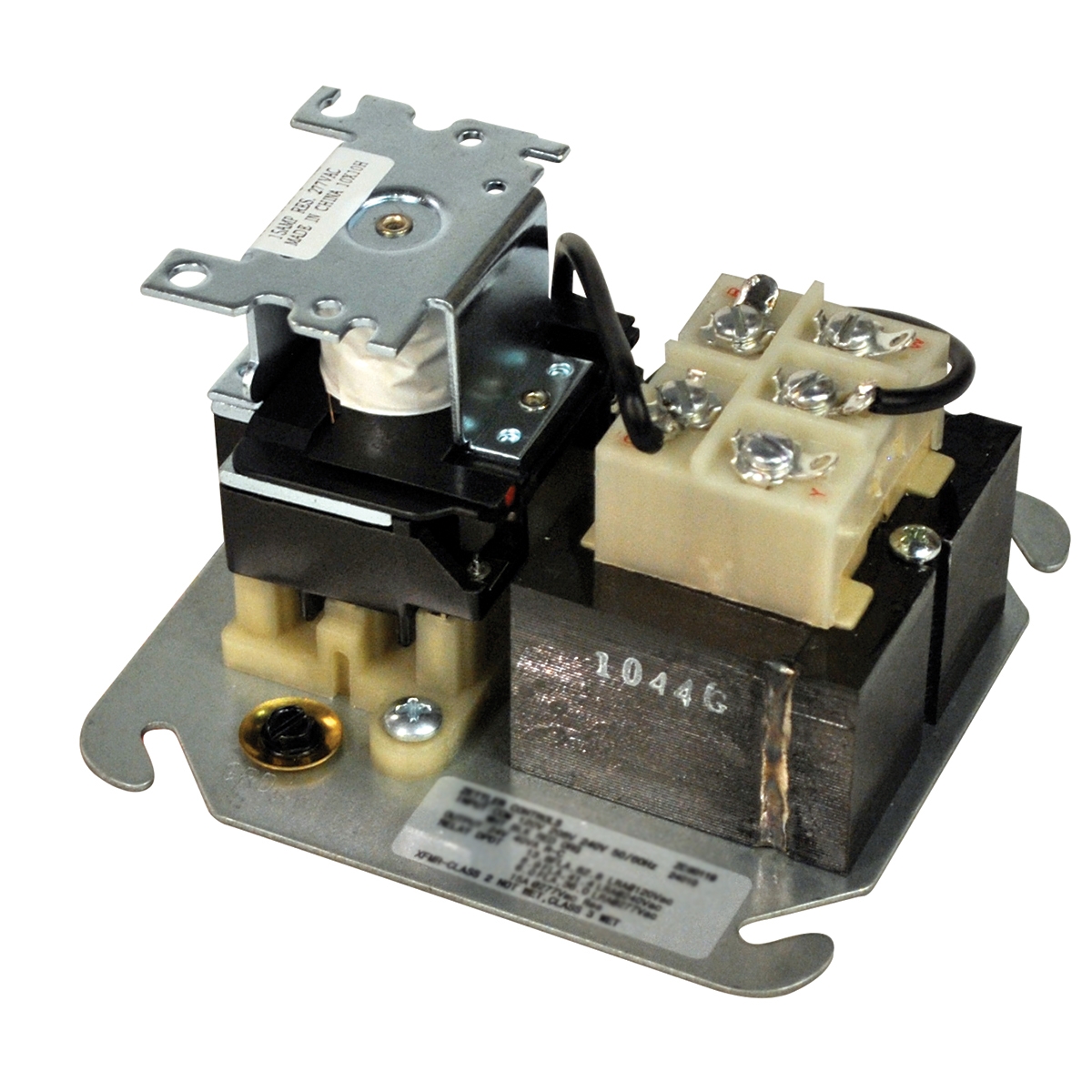
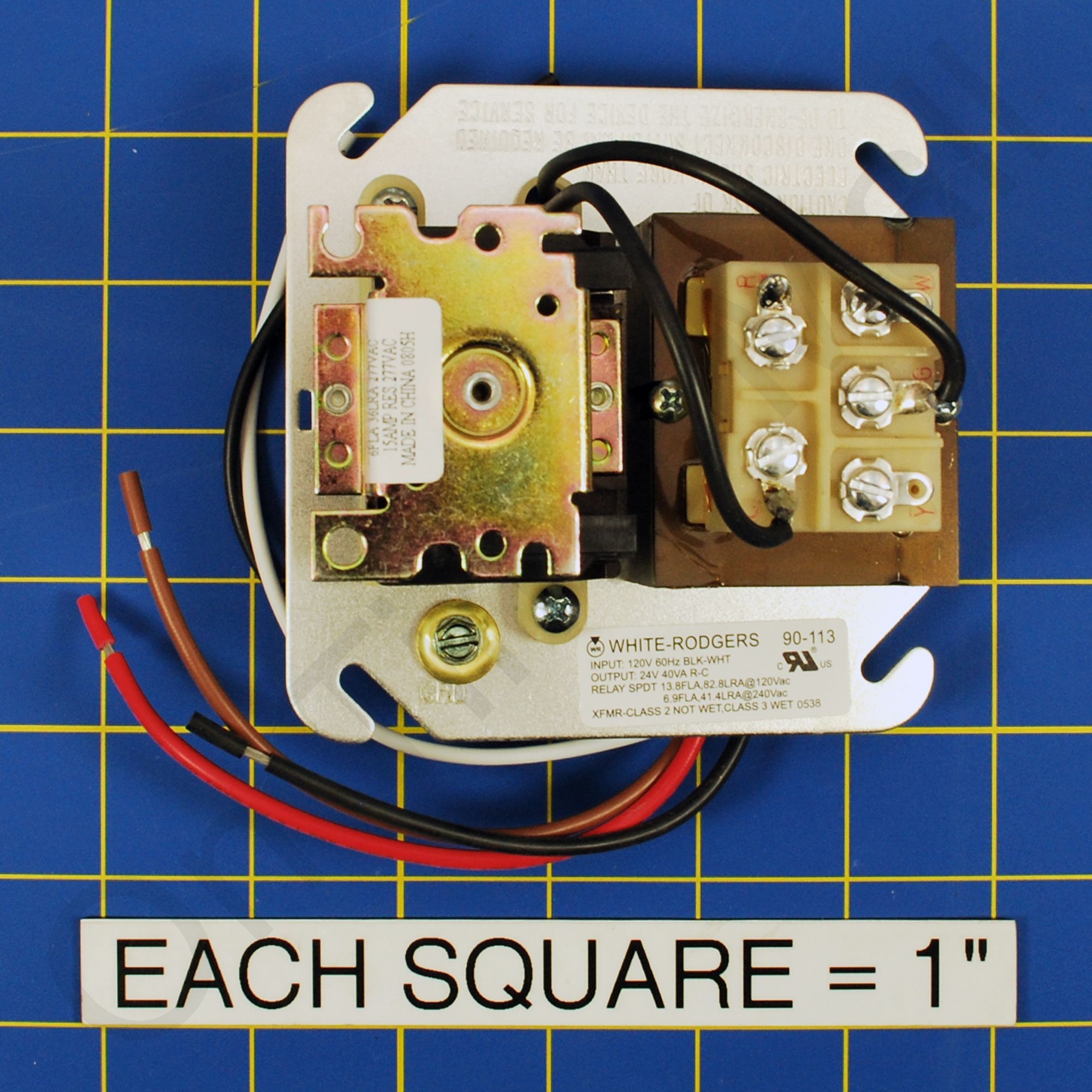
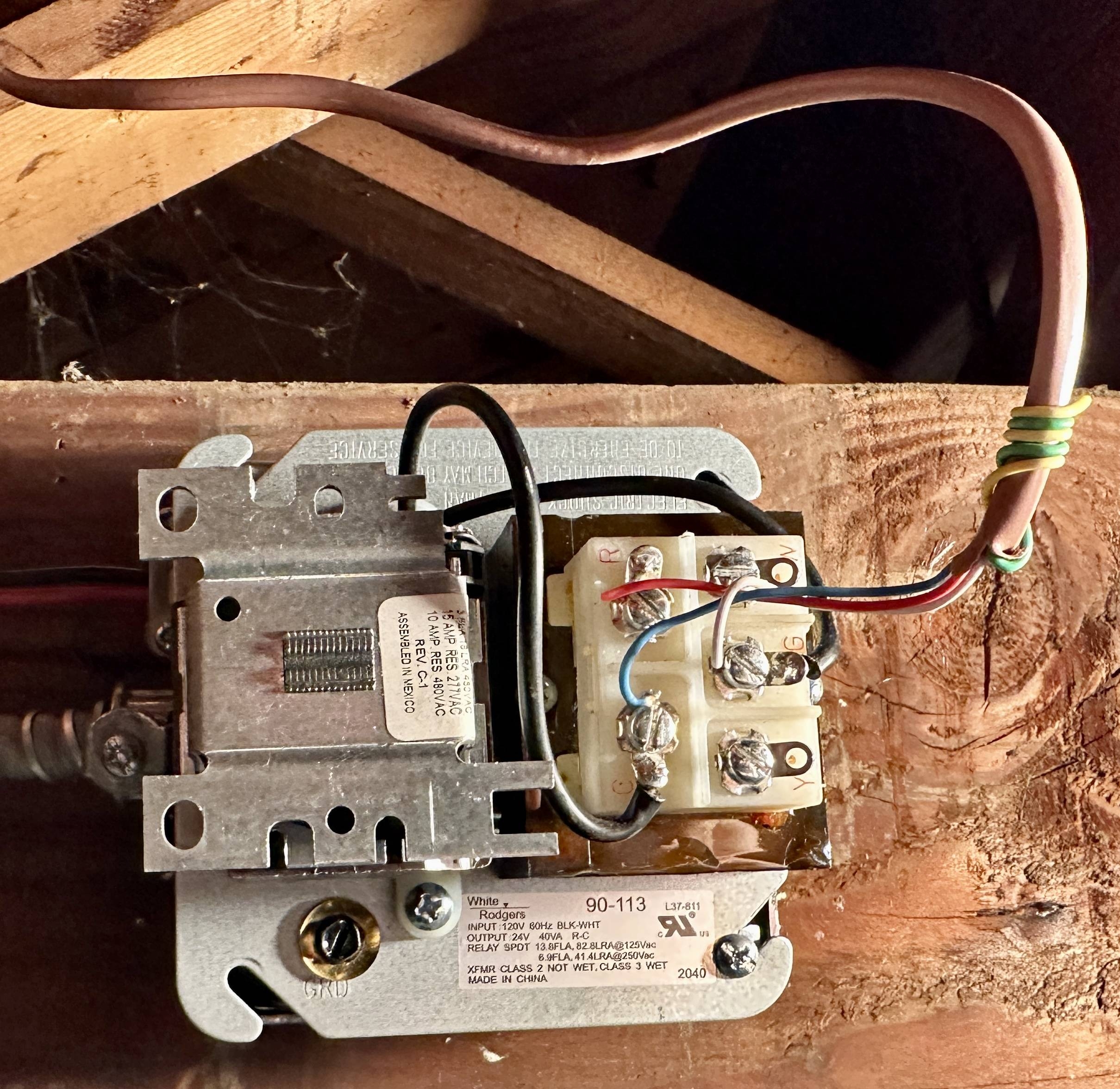
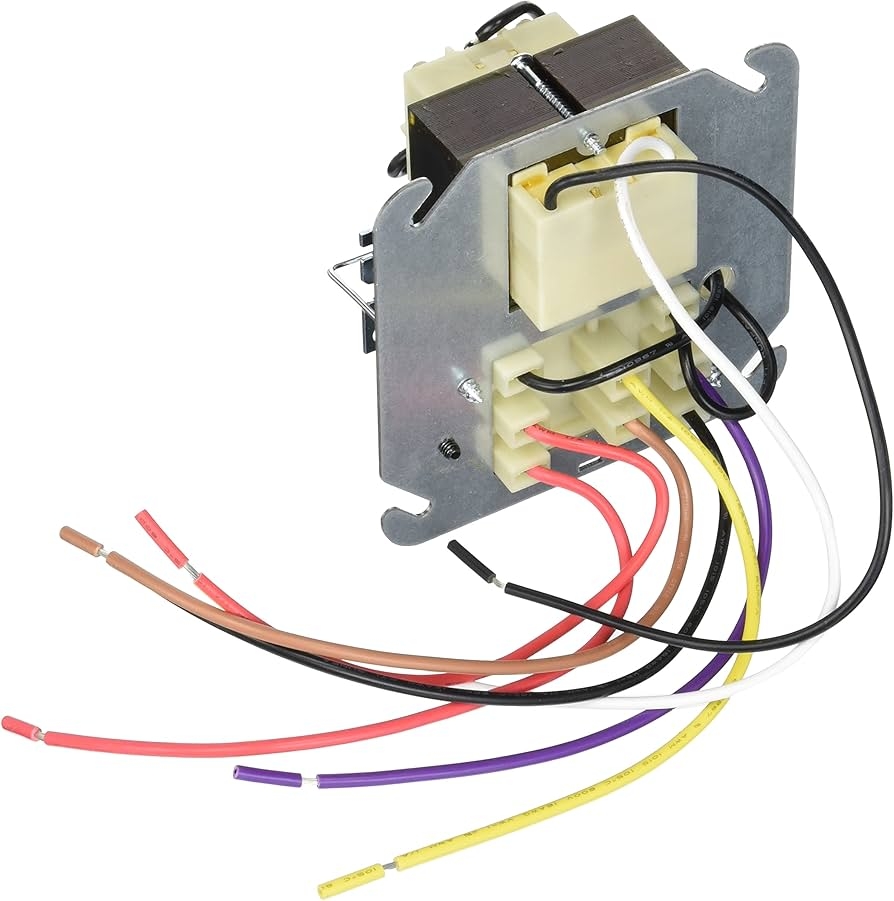
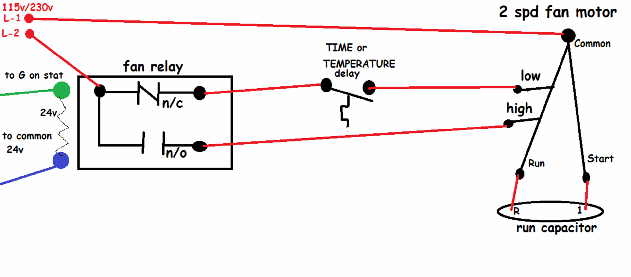
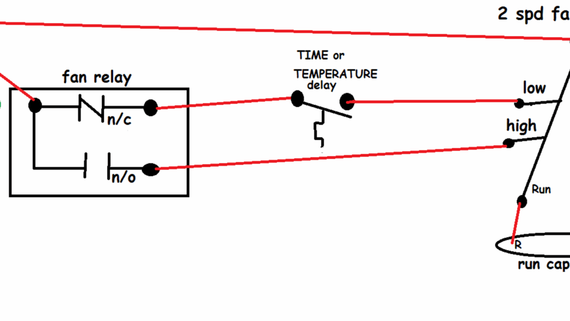
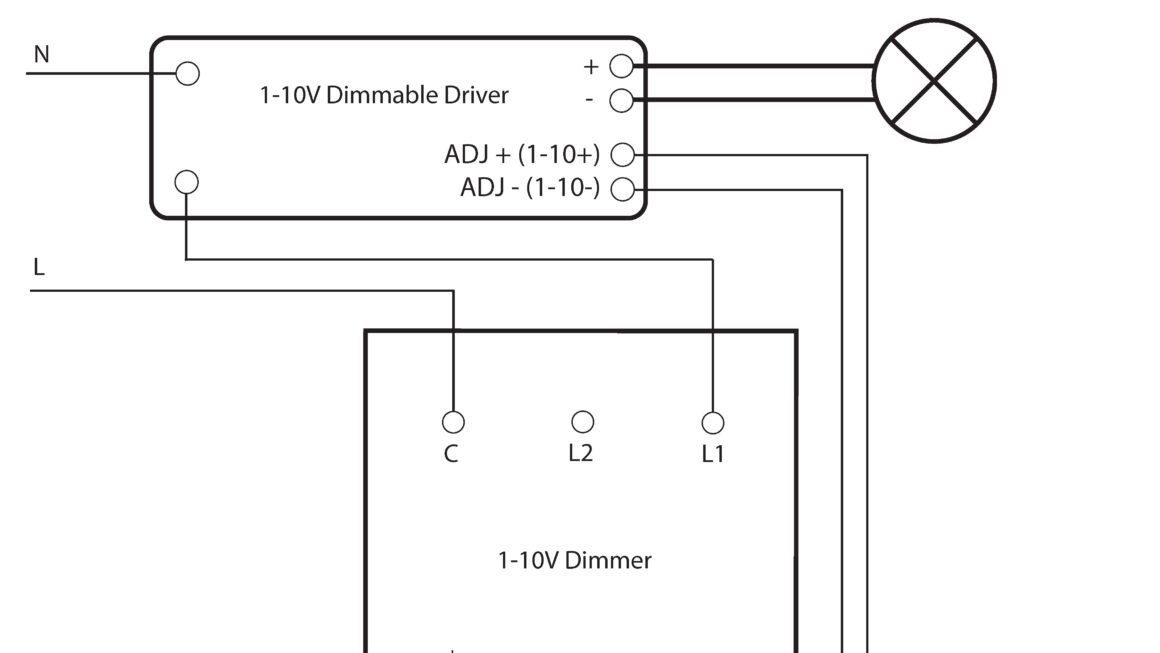
The 90-113 boiler wiring diagram typically includes details on the power supply, control circuit, safety devices, and other components. It shows how these parts are connected and how electricity flows through the system.
By studying the wiring diagram, technicians can troubleshoot issues, make repairs, or install new components with confidence. It’s a valuable tool that helps ensure the boiler operates safely and efficiently.
It’s important to follow the manufacturer’s instructions and guidelines when working with boiler wiring diagrams. Safety should always be the top priority to prevent accidents and ensure the longevity of the equipment.
In conclusion, the 90-113 boiler wiring diagram is a crucial piece of information for anyone working with boilers. Understanding how the electrical components are connected can help ensure the proper functioning of the system and prevent potential hazards.
Download and Print 90-113 Boiler Wiring Diagram Listed below
