If you’re looking to install a new air conditioning system or replace an old one, understanding how to wire a capacitor is crucial. A C capacitor wiring diagram can help you navigate this process with ease.
Capacitors are essential components in air conditioning systems that store and release energy to help the motor start and run smoothly. Without a properly wired capacitor, your AC unit may not function efficiently or may even fail to start altogether.

Related Post Three Phase Electric Motor Wiring Diagram
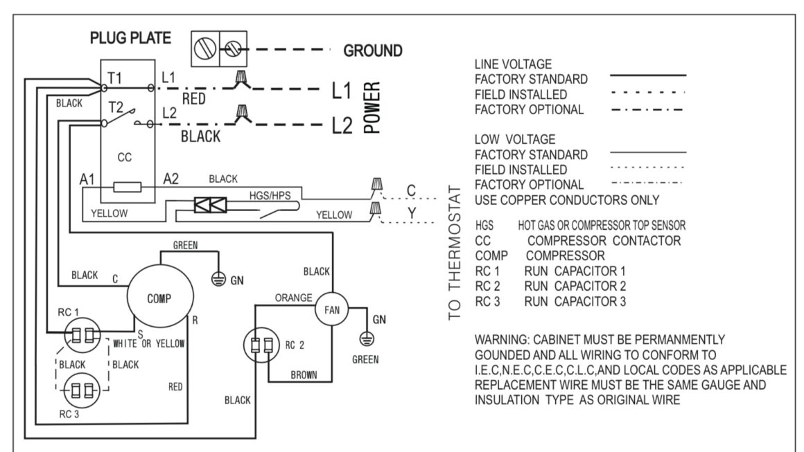
Typically, a capacitor will have three terminals: Herm (compressor), Fan, and C (common). Each terminal must be connected to the corresponding terminal on the motor and power source to ensure proper functioning of the system.
Before starting the wiring process, make sure to turn off the power to the AC unit to prevent any accidents. You may also want to use a multimeter to test the capacitor and ensure it is functioning correctly before installation.
Once you have successfully wired the capacitor according to the diagram, double-check all connections to ensure they are secure. After everything is in place, you can turn the power back on and test the AC unit to see if it starts up and runs smoothly.
Remember, if you’re unsure about how to wire a capacitor or encounter any issues during the process, it’s best to consult a professional HVAC technician for assistance. They have the knowledge and expertise to tackle any wiring issues and ensure your AC system operates efficiently.
By following a proper A C capacitor wiring diagram and taking necessary precautions, you can ensure your air conditioning system runs smoothly and efficiently, keeping you cool and comfortable during the hot summer months.
Download and Print A C Capacitor Wiring Diagram Listed below