Are you looking to understand how to wire your air conditioner contactor? Look no further! In this article, we will provide you with a detailed Air Conditioner Contactor Wiring Diagram to help you tackle this task with confidence.
Understanding the wiring diagram for your air conditioner contactor is crucial for ensuring that your unit operates efficiently. By following the correct wiring instructions, you can avoid potential issues and keep your AC system running smoothly.

Related Post Western Snow Plow Wiring Diagram
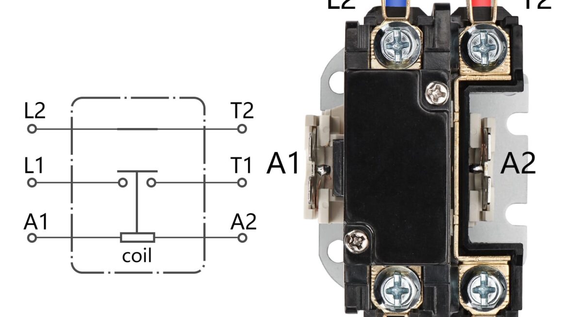
Once you have located the contactor, you will need to identify the different terminals on it. Typically, a contactor will have at least three terminals: one for power in, one for power out to the compressor, and one for power out to the condenser fan motor.
Next, you will need to refer to the wiring diagram for your specific air conditioner model. This diagram will provide you with a visual representation of how to connect the different wires to the corresponding terminals on the contactor. It’s crucial to follow this diagram carefully to ensure proper installation.
After connecting the wires according to the wiring diagram, it’s important to double-check your work to ensure that everything is properly connected. Once you have confirmed that the wiring is correct, you can test your air conditioner to see if it is functioning correctly.
In conclusion, understanding the Air Conditioner Contactor Wiring Diagram is essential for proper installation and operation of your air conditioning unit. By following the instructions provided in the diagram and double-checking your work, you can ensure that your AC system runs efficiently and effectively.
Download and Print Air Conditioner Contactor Wiring Diagram Listed below

Related Post On Off On Toggle Switch Wiring Diagram