Are you looking to install a boat switch panel but unsure of how to wire it up? Don’t worry, we’ve got you covered! In this article, we’ll walk you through a boat switch panel wiring diagram, making the process easy to understand and follow.
Before we dive into the wiring diagram, let’s first understand what a boat switch panel is. A switch panel is a centralized location on your boat where you can control various electrical components such as lights, pumps, and electronics. It helps to streamline the operation of these devices, making your boating experience more convenient.

Related Post Wiring Diagram 3 Way Switch Power To Light
Next, determine the electrical components you want to connect to the switch panel. This could include navigation lights, bilge pumps, or any other accessories on your boat. Each component should have its own dedicated wire connected to the switch panel, making sure to match the positive and negative terminals correctly.
It’s important to use the right gauge wire for your boat switch panel to handle the electrical load safely. Refer to the manufacturer’s instructions or a wiring diagram specific to your boat model to ensure you’re using the correct wire size. This will help prevent overheating and potential electrical hazards.
Once you have connected all the wires to the switch panel, double-check your work to make sure everything is secure and properly insulated. Test each switch to ensure that it activates the corresponding component without any issues. If everything is working correctly, you’re all set to enjoy your newly installed boat switch panel!
In conclusion, wiring a boat switch panel doesn’t have to be complicated. By following a wiring diagram and taking the time to connect each component correctly, you can ensure a smooth and hassle-free installation process. So, grab your tools and get ready to upgrade your boat’s electrical system with a switch panel today!
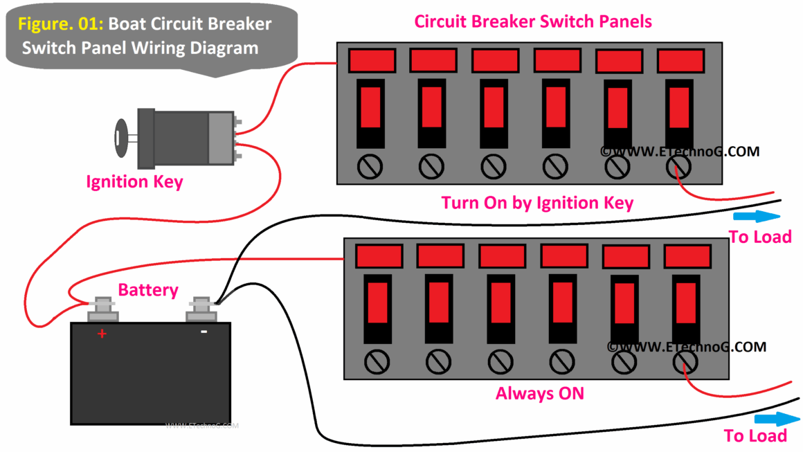
Download and Print Boat Switch Panel Wiring Diagram Listed below