If you’re looking to install or troubleshoot your Chamberlain garage door sensor, you’ve come to the right place. Understanding the wiring diagram is key to ensuring everything works smoothly.
When it comes to Chamberlain garage door sensor wiring diagrams, it’s important to follow the instructions carefully. These diagrams provide a visual representation of how the sensors should be connected for optimal functionality.

Related Post Trailer Light Wiring Diagram 7 Pin
Before starting the wiring process, make sure to turn off the power to the garage door opener to avoid any accidents. Follow the color-coding on the diagram to match the wires correctly and securely fasten them in place.
If you’re having trouble understanding the wiring diagram or need assistance with the installation, don’t hesitate to consult the Chamberlain manual or reach out to their customer support team. It’s always better to seek help than risk damaging the sensors.
By following the Chamberlain garage door sensor wiring diagram accurately, you can ensure that your garage door operates smoothly and safely. Proper installation and maintenance of the sensors are crucial in preventing accidents and keeping your property secure.
So, next time you’re working on your Chamberlain garage door sensor system, refer back to the wiring diagram to guide you through the process. With the right tools and knowledge, you can have your sensors up and running in no time!
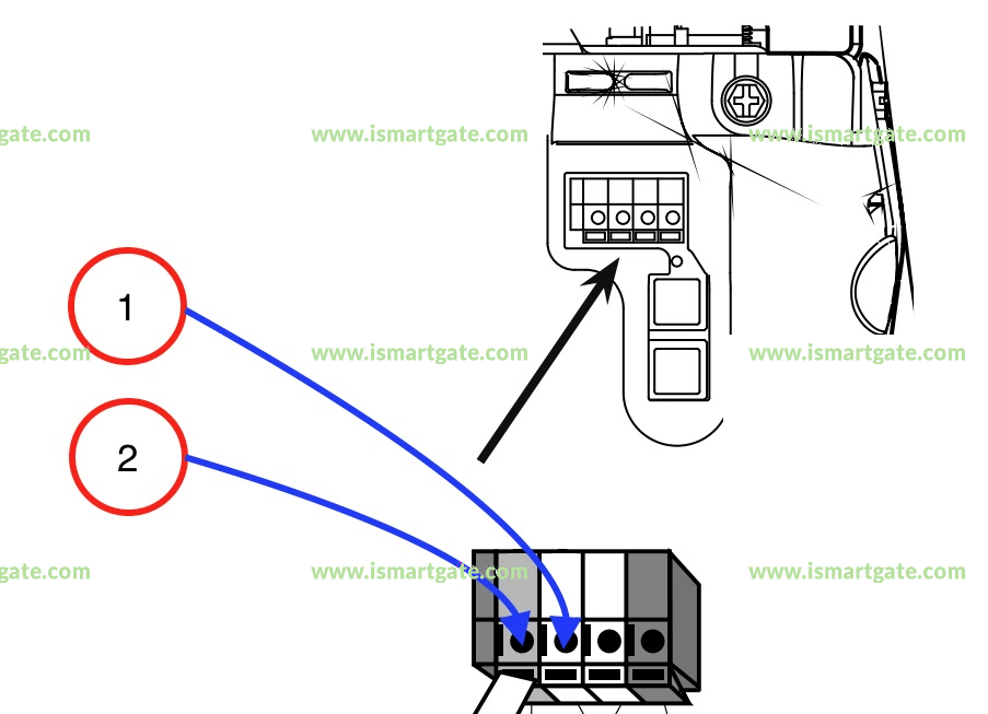
Download and Print Chamberlain Garage Door Sensor Wiring Diagram Listed below