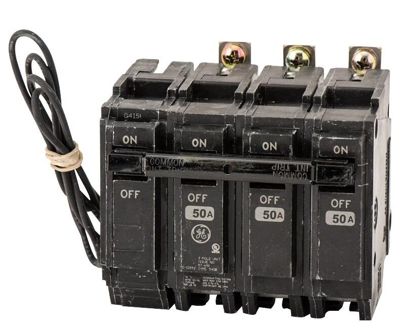
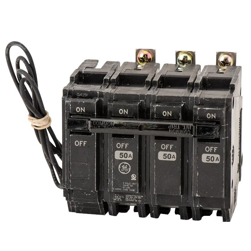
If you’re in the process of installing a circuit breaker shunt trip, understanding the wiring diagram is crucial. This diagram serves as a guide to ensure the proper connection and functioning of the shunt trip mechanism.
By following the circuit breaker shunt trip wiring diagram, you can easily identify the different components involved and how they should be connected. This will help prevent any potential issues or malfunctions in the future.
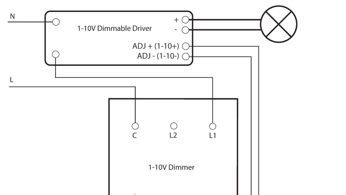
Related Post Wiring Diagram For Dimmer Switch
Before starting the wiring process, make sure to carefully read and understand the wiring diagram provided by the manufacturer. This will help you avoid any mistakes and ensure a safe and efficient installation.
Once you have successfully connected all the components according to the wiring diagram, it’s essential to test the shunt trip mechanism to confirm that it is working correctly. This test will help identify any potential issues that need to be addressed before putting the circuit breaker into operation.
In conclusion, understanding the circuit breaker shunt trip wiring diagram is essential for a successful installation process. By following the diagram accurately and conducting thorough testing, you can ensure the safety and reliability of your electrical system.
