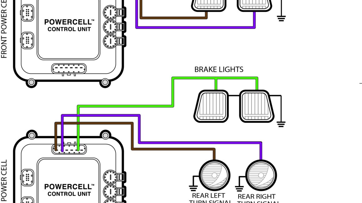
If you’re looking to upgrade your motorcycle’s brake and turn signal system, understanding the wiring diagram is crucial. By combining these two functions, you can streamline your bike’s electrical system for a more efficient and safer ride.
Having a clear understanding of the combined brake and turn signal wiring diagram will not only help you install the new system correctly but also troubleshoot any issues that may arise in the future.

Related Post 12 Volt Amp Meter Wiring Diagram
Typically, the brake light wire is red, the turn signal wire is green or yellow, and the ground wire is black or brown. By following the color-coding and the diagram provided by the manufacturer, you can easily connect the wires to the appropriate components.
It’s crucial to double-check your connections before testing the system to ensure everything is properly installed. Once you’ve confirmed that the wiring is correct, test the brake and turn signal functions to make sure they are working as intended.
If you encounter any issues, such as lights not turning on or flashing incorrectly, refer back to the wiring diagram to troubleshoot the problem. It’s essential to have a good understanding of the diagram to identify and fix any wiring issues effectively.
In conclusion, understanding the combined brake and turn signal wiring diagram is essential for anyone looking to upgrade their motorcycle’s electrical system. By following the provided diagram and color-coding, you can ensure a smooth installation process and enjoy a safer and more efficient ride on your bike.
Download and Print Combined Brake And Turn Signal Wiring Diagram Listed below