Have you ever wondered how the electrical wiring diagram of a motorcycle works? Understanding the wiring system of your bike can help you troubleshoot any issues that may arise.
Electrical systems in motorcycles are crucial for proper functioning, from powering the lights and indicators to starting the engine. Having a basic knowledge of the wiring diagram can come in handy when dealing with electrical problems.

Related Post Trailer Plug Wiring Diagram 7 Way
The battery stores electrical energy, which is used to power the various electrical components of the motorcycle. The alternator generates electricity as the engine runs, replenishing the battery’s charge and keeping the electrical system operational.
The regulator/rectifier regulates the voltage output from the alternator to prevent overcharging the battery. It also converts the AC current generated by the alternator into DC current, which is used by the motorcycle’s electrical components.
The ignition switch controls the flow of electricity from the battery to the various components of the motorcycle. Turning the key activates the electrical system, allowing the engine to start and the lights to turn on.
In conclusion, understanding the electrical wiring diagram of your motorcycle can save you time and money when diagnosing electrical issues. By familiarizing yourself with the various components and their functions, you can tackle minor problems on your own and keep your bike running smoothly.
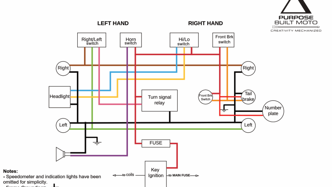
Download and Print Electrical Wiring Diagram Of Motorcycle Listed below