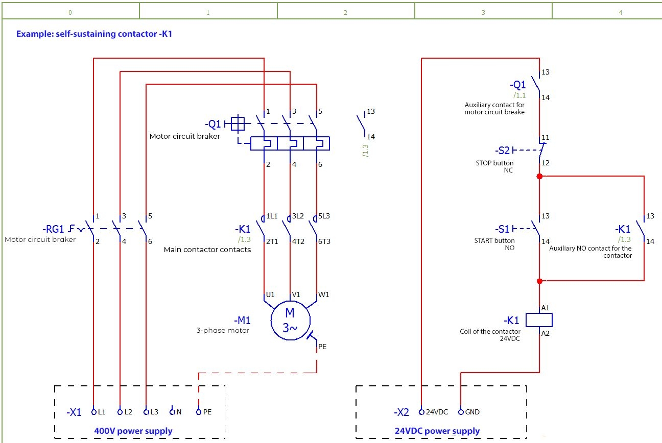
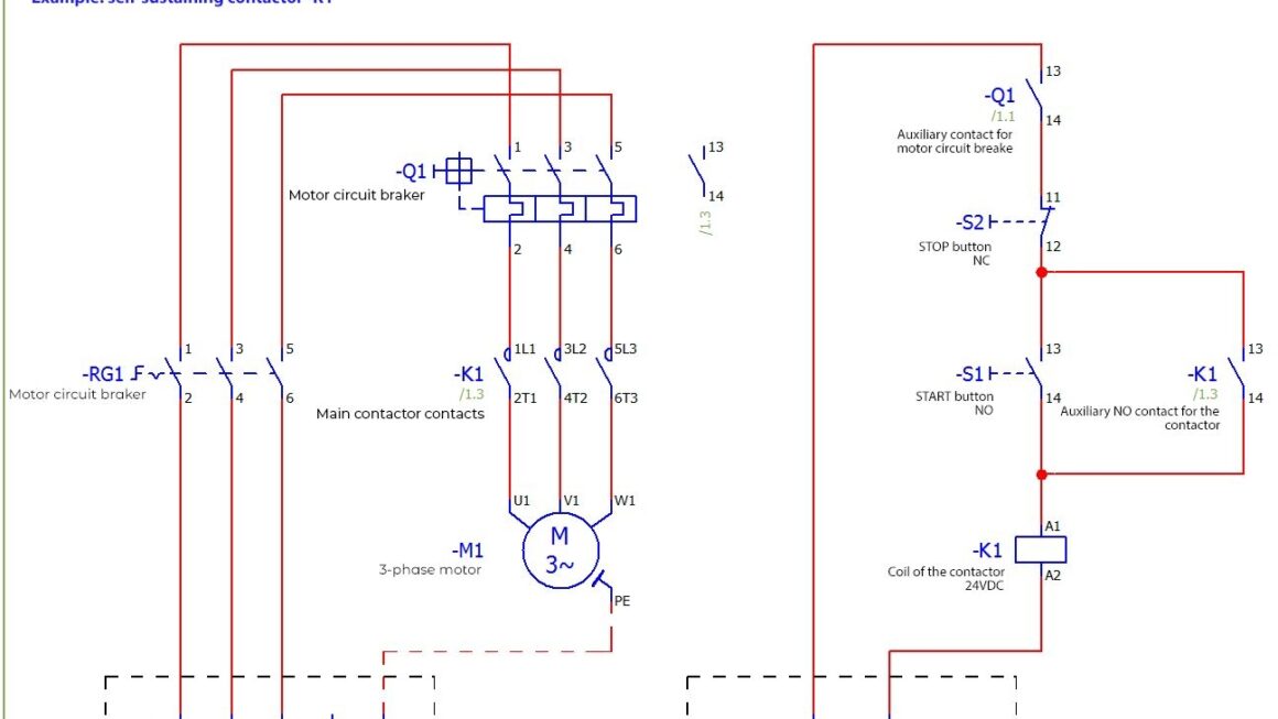
Are you looking to understand electrical wiring diagrams for contactors? You’ve come to the right place! In this article, we will break down the basics of electrical wiring diagrams for contactors in a way that is easy to understand.
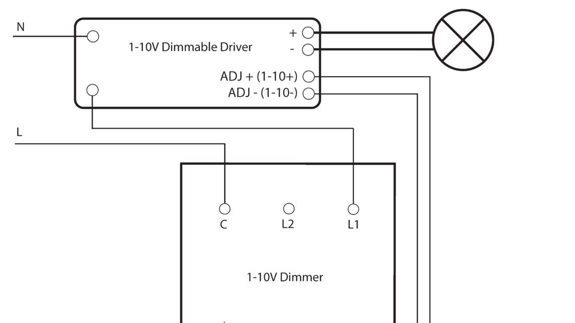
Electrical wiring diagrams for contactors are essential for understanding how electrical circuits work. They show the connections between various components, such as switches, relays, and contactors, allowing you to troubleshoot issues and make necessary repairs.
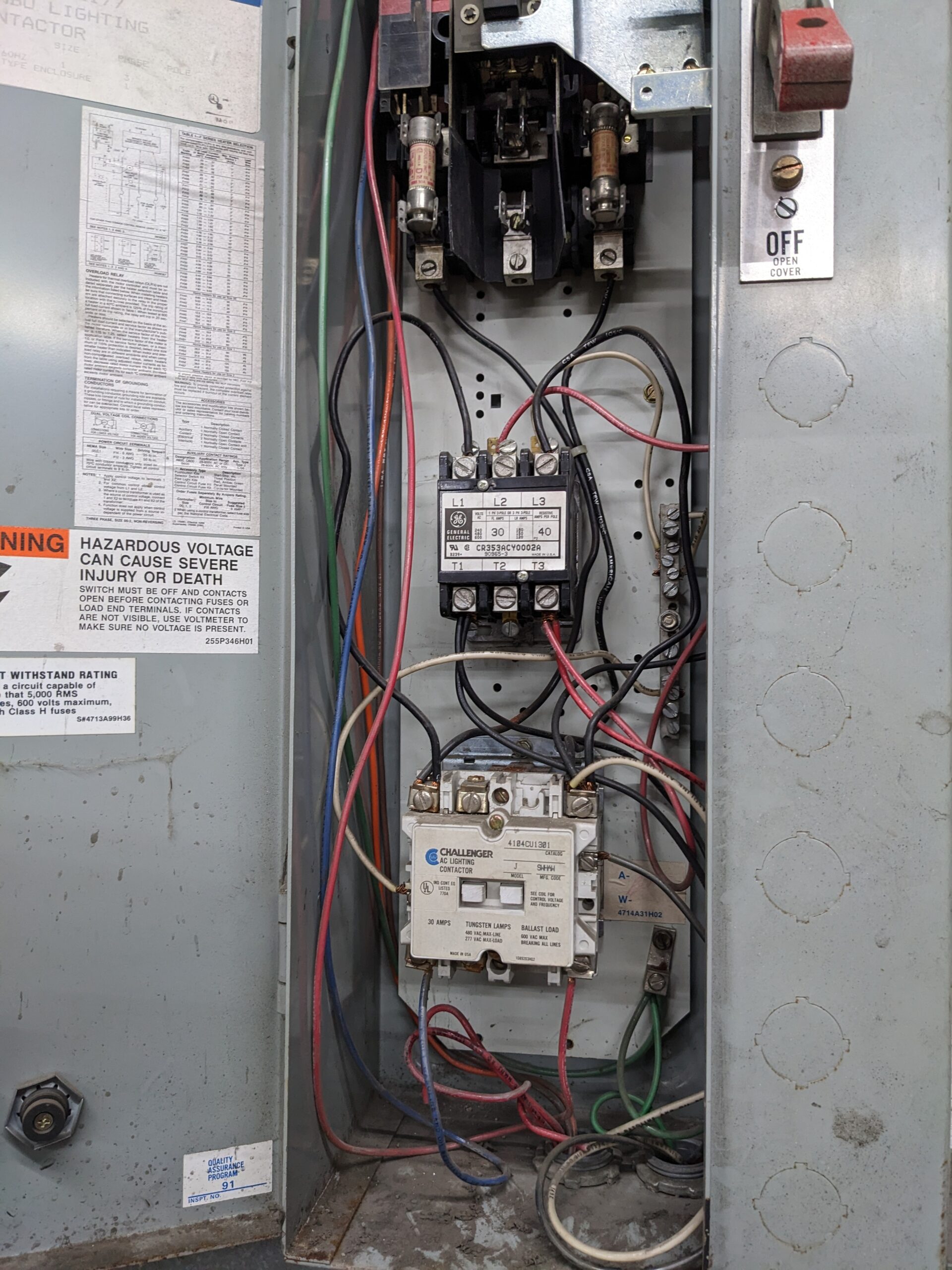
Related Post 5 Pin Rocker Switch Wiring Diagram
Additionally, electrical wiring diagrams for contactors help electricians and technicians follow safety protocols when working on electrical systems. By understanding the diagram, they can safely make repairs and installations without risking their safety or damaging the equipment.
In conclusion, electrical wiring diagrams for contactors are a valuable resource for anyone working with electrical systems. By understanding how to read and interpret these diagrams, you can effectively troubleshoot issues, make necessary repairs, and ensure the safety of the electrical system.
Next time you come across an electrical wiring diagram for contactors, don’t be intimidated. Take the time to study the diagram, understand the components, and follow the connections. With practice, you’ll become more proficient in reading and interpreting these diagrams, making you a more skilled electrician or technician.
Download and Print Electrical Wiring Diagrams For Contactors Listed below
