When it comes to installing a Fisher plow solenoid, having the correct wiring diagram is crucial. Without it, you may encounter issues that can be frustrating and time-consuming to troubleshoot.
One common problem that arises from incorrect wiring is the solenoid not functioning properly, leading to the plow not moving as it should. This can result in delays and added expenses to fix the issue.

Related Post 7 Pin Trailer Wiring Diagram With Brakes
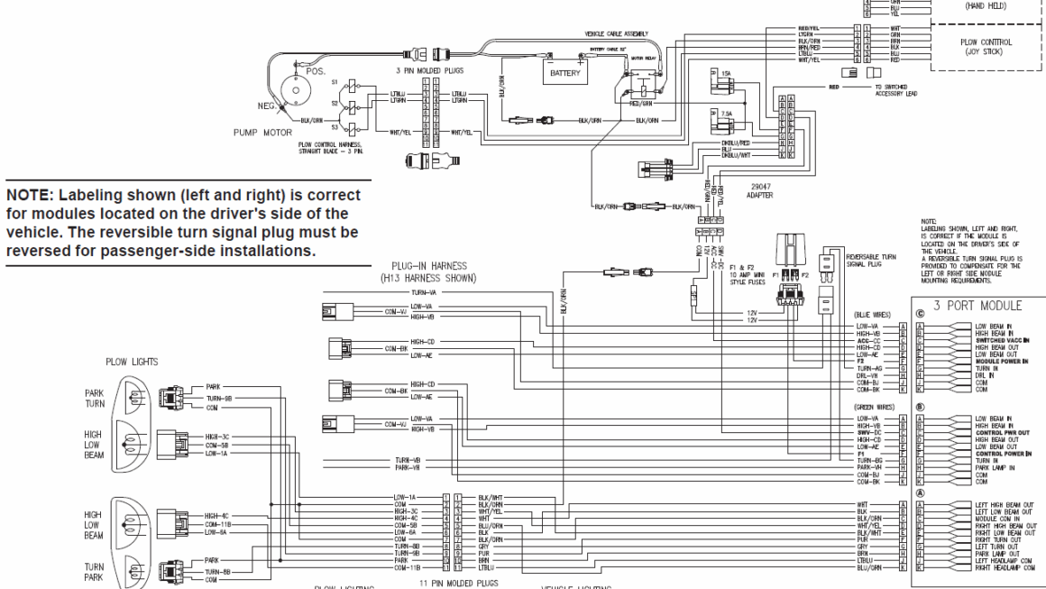
Start by identifying the power source, ground, and control wires. Then, carefully connect each wire to its designated terminal on the solenoid. Double-check your connections before testing the plow to avoid any unnecessary complications.
By following the Fisher plow solenoid wiring diagram accurately, you can save yourself time and frustration in the long run. It’s a simple yet crucial step that can make a significant difference in the performance of your plow.
Remember, safety should always be a top priority when working with electrical components. Make sure to disconnect the battery before starting any wiring work and wear appropriate protective gear to prevent accidents.
With the right tools and knowledge, installing a Fisher plow solenoid can be a straightforward process. Just take your time, follow the wiring diagram carefully, and you’ll have your plow up and running in no time!
In conclusion, having the correct Fisher plow solenoid wiring diagram is essential for a successful installation. By following the provided instructions and taking necessary safety precautions, you can ensure a smooth and trouble-free process. Don’t overlook this crucial step and enjoy a well-functioning plow for years to come!
Download and Print Fisher Plow Solenoid Wiring Diagram Listed below