Have you ever wondered how your garage door sensor works? Understanding the wiring diagram can help you troubleshoot any issues that may arise. Let’s take a closer look at the garage door sensor wiring diagram and how it functions.
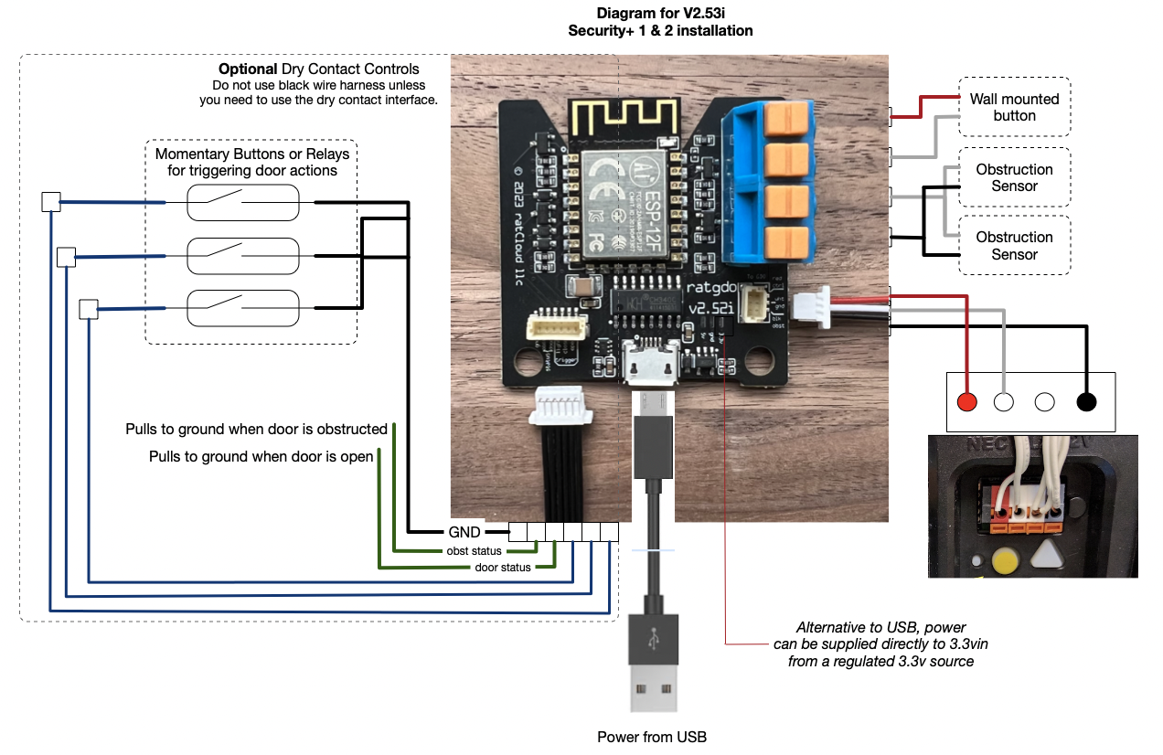
Garage door sensors are an essential safety feature that prevents the door from closing on objects or people in its path. The wiring diagram shows how the sensors are connected to the opener and how they communicate to ensure safe operation.

Related Post 4 Wire Lambda Sensor Wiring Diagram
Each sensor has two wires that connect to the opener unit. One wire is for power, while the other is for the signal. It’s crucial to follow the wiring diagram carefully to ensure proper installation and functionality of the sensors.
If you’re experiencing issues with your garage door sensors, checking the wiring diagram can help pinpoint the problem. Common issues include misaligned sensors, damaged wires, or faulty connections. By referring to the diagram, you can troubleshoot and resolve these issues efficiently.
Regular maintenance of your garage door sensors is essential to ensure they are functioning correctly. Inspect the wiring for any signs of wear or damage, and clean the sensors regularly to maintain optimal performance. Following the wiring diagram can help you keep your garage door system in top condition.
In conclusion, understanding the garage door sensor wiring diagram is crucial for maintaining the safety and functionality of your garage door system. By familiarizing yourself with the diagram and performing regular maintenance, you can ensure smooth operation and peace of mind knowing your garage door is safe for use.
Download and Print Garage Door Sensor Wiring Diagram Listed below