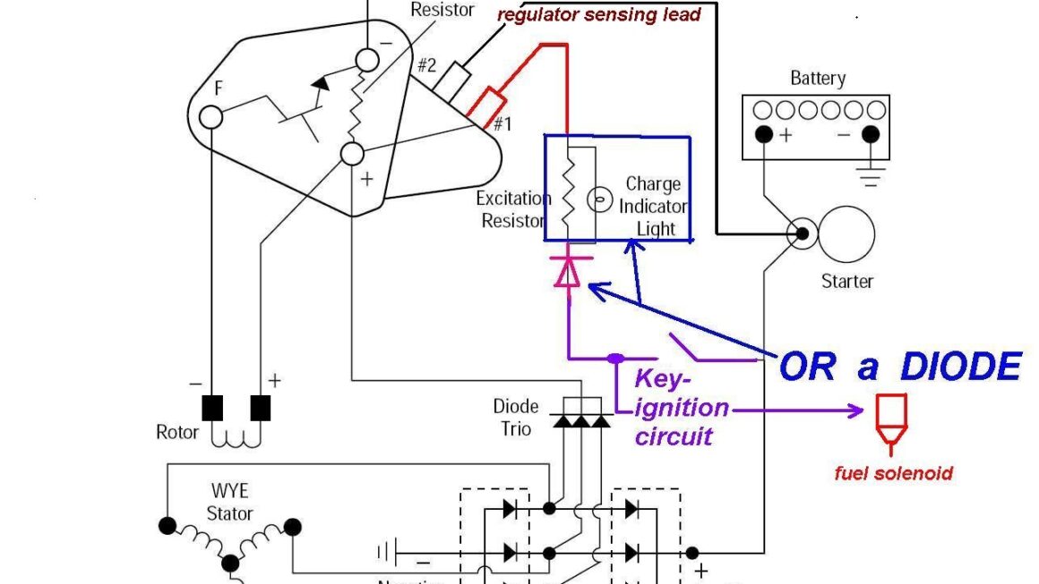
Are you looking for a simple and easy-to-understand Internal Regulator 3 Wire Alternator Wiring Diagram? Look no further! In this article, we will break down the wiring diagram for you in a way that is clear and concise.
Understanding how to wire a 3 wire alternator with an internal regulator can be confusing, but with the right diagram, it can be a breeze. Whether you are a seasoned mechanic or a DIY enthusiast, having a good wiring diagram is essential.

Related Post 3 Wire 220V Welder Plug Wiring Diagram
The second wire is the “S” terminal, which is used to sense the voltage level in the system. This wire is connected to the ignition switch and provides the necessary voltage to activate the alternator.
Lastly, the third wire is the “L” terminal, which is used for the warning light on the dashboard. This wire is connected to the warning light and provides a signal to the driver if there is an issue with the charging system.
By following a clear wiring diagram for your Internal Regulator 3 Wire Alternator, you can ensure that your charging system is working efficiently and effectively. Whether you are replacing an old alternator or installing a new one, having a good wiring diagram is key to a successful installation.
In conclusion, having a solid understanding of the Internal Regulator 3 Wire Alternator Wiring Diagram is crucial for anyone working on their vehicle’s charging system. By following the correct wiring diagram, you can ensure that your alternator is working properly and keeping your battery charged. So, next time you are working on your car, make sure to refer to a reliable wiring diagram to guide you through the process.
Download and Print Internal Regulator 3 Wire Alternator Wiring Diagram Listed below