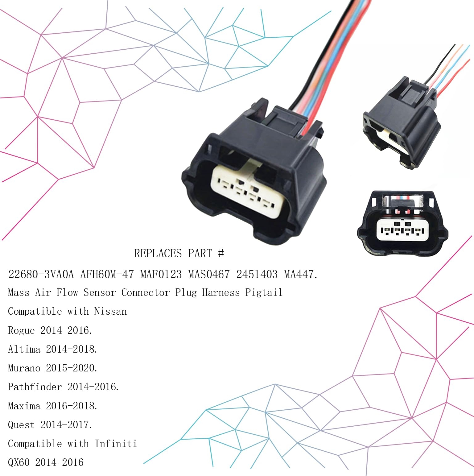
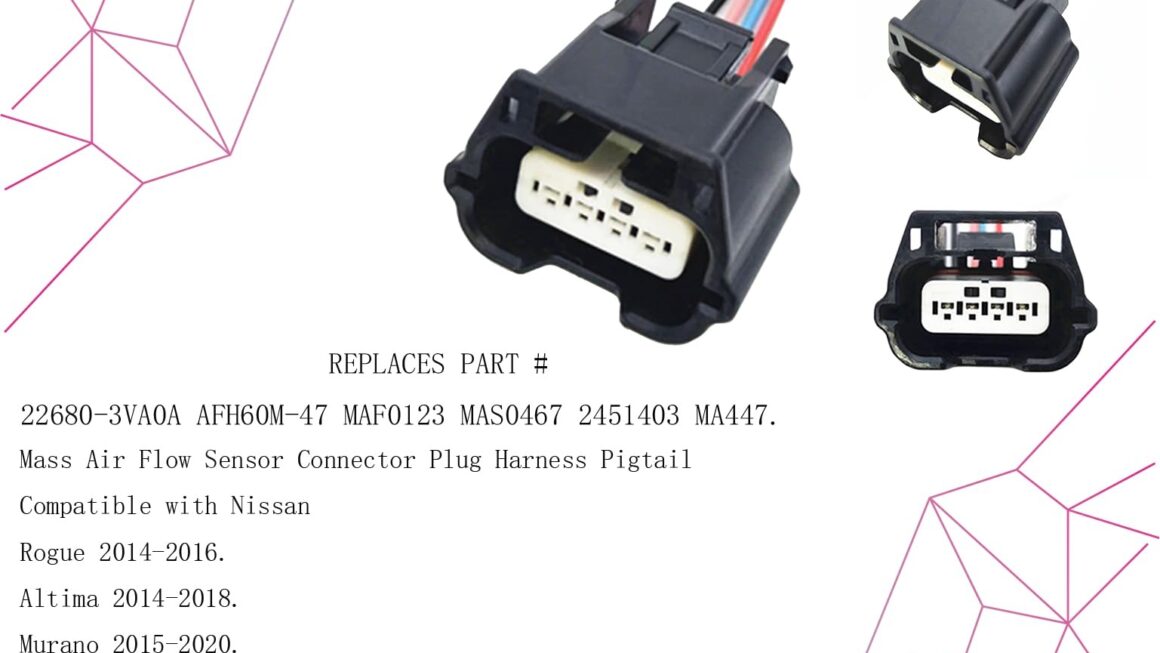
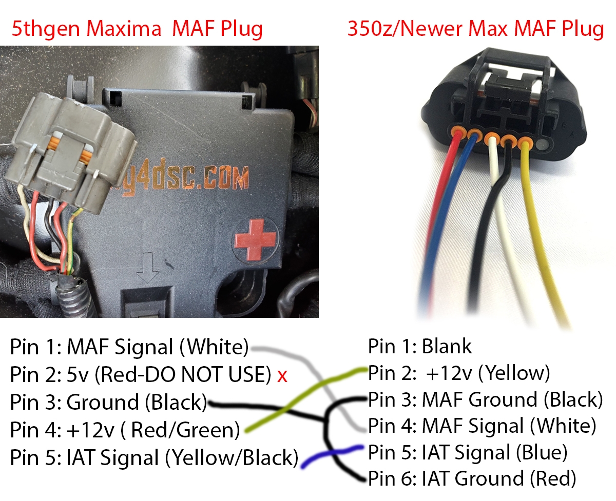
If you’re having issues with your car’s engine performance, the mass air flow sensor could be the culprit. Understanding how to properly wire it can make all the difference in getting your vehicle running smoothly again.
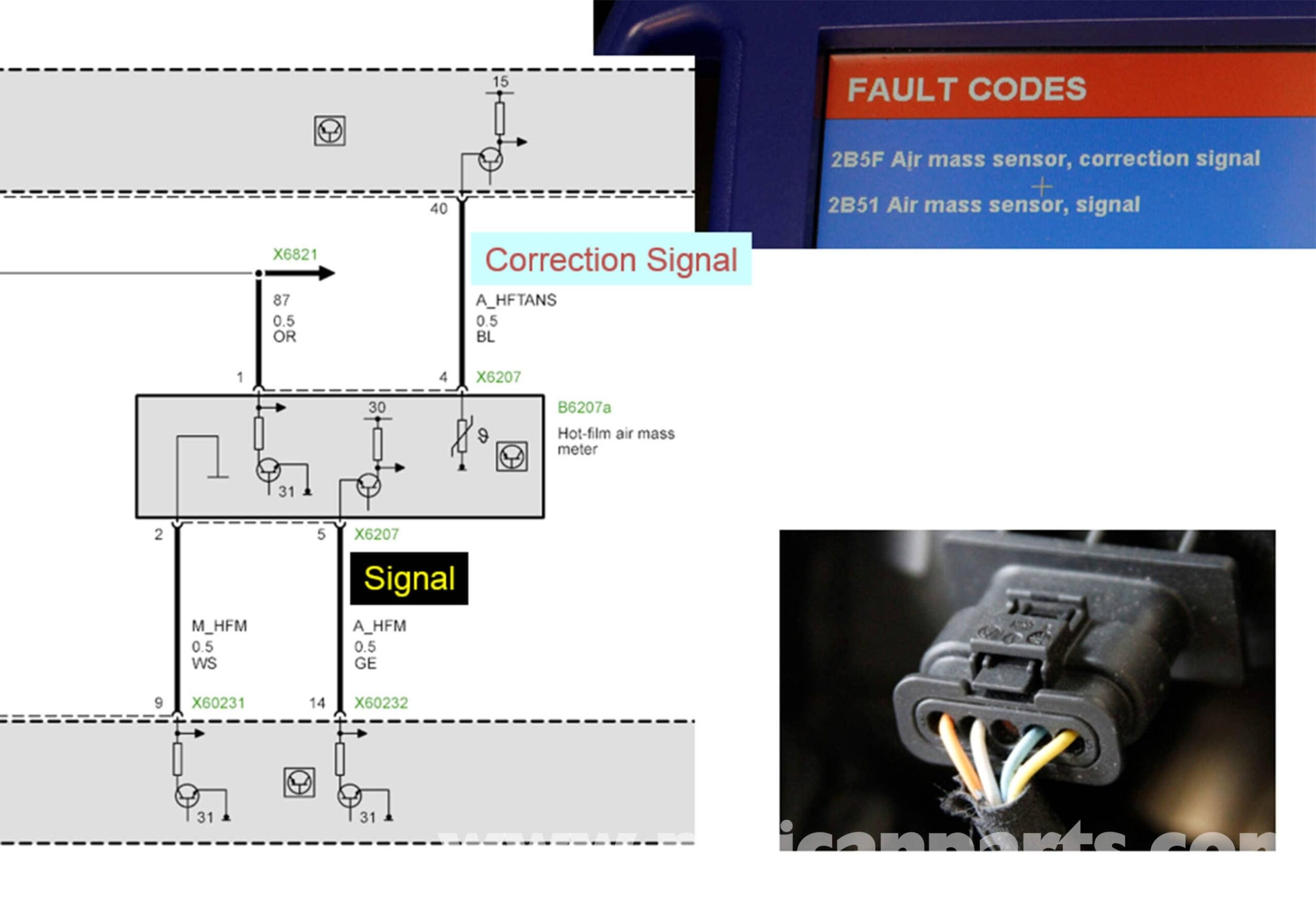
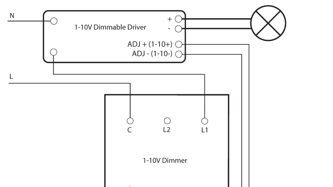
Whether you’re a seasoned mechanic or a DIY enthusiast, having a good wiring diagram for the mass air flow sensor is essential. It will help you identify any potential issues and make the necessary repairs quickly and effectively.
Related Post Goldtop Lp One Pickup 50'S Wiring Diagram
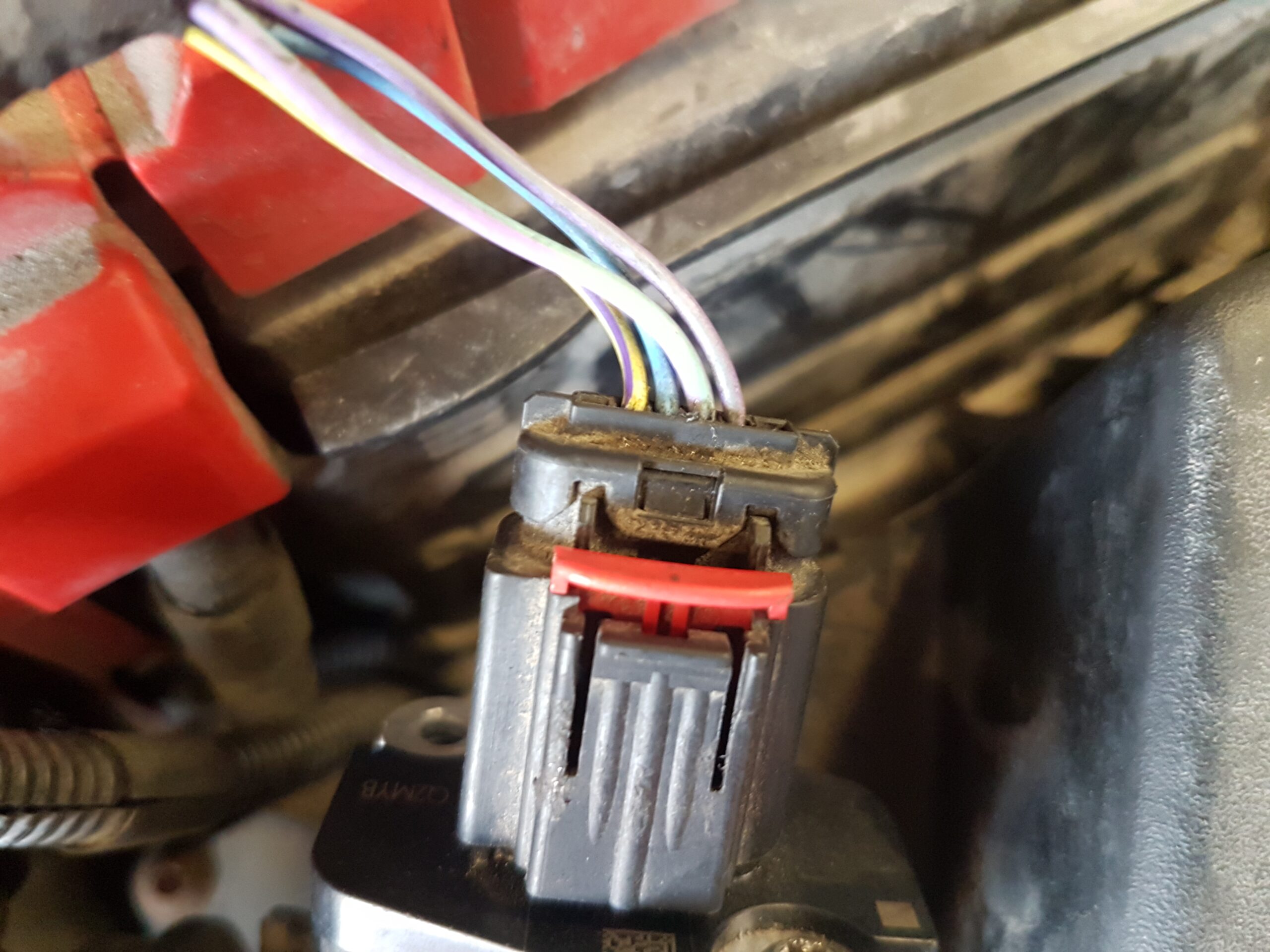
Start by locating the mass air flow sensor in your vehicle. It is usually located near the air filter box or the intake manifold. Once you have located it, carefully inspect the wiring harness to determine if there are any visible signs of damage or wear.
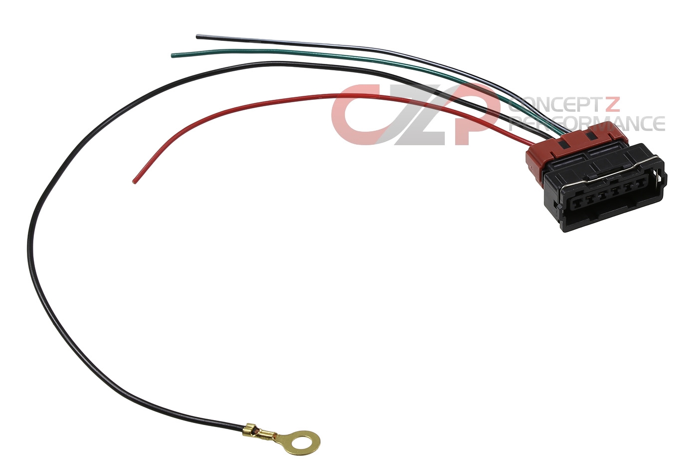
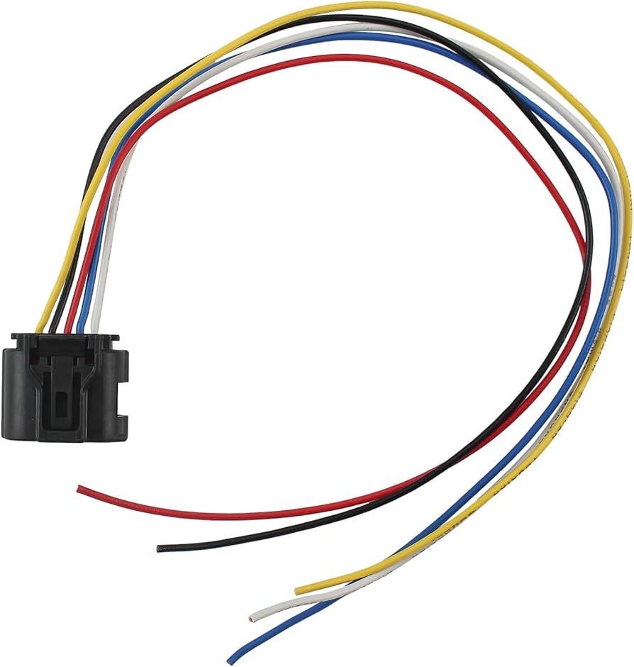
If you need to replace any wires, make sure to use the correct gauge and color to match the existing wiring. This will help prevent any confusion and ensure that the sensor functions properly once everything is connected.
After you have successfully wired the mass air flow sensor according to the diagram, don’t forget to double-check your work. Start your engine and test the sensor to make sure that it is functioning correctly. If everything looks good, you’re all set!
By following a proper wiring diagram for your mass air flow sensor, you can save yourself time and money in the long run. Don’t hesitate to reach out to a professional if you’re unsure about any steps in the process. It’s always better to be safe than sorry when it comes to your vehicle’s performance.
Keep your car running smoothly by ensuring that the mass air flow sensor is properly wired. With the right diagram and a little bit of know-how, you’ll be back on the road in no time!
Download and Print Mass Air Flow Sensor Wiring Diagram Listed below
