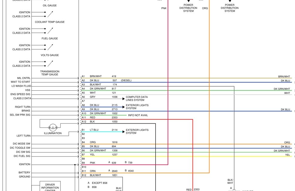
If you’re looking for a Pinout GM instrument cluster wiring diagram, you’ve come to the right place. Understanding the wiring diagram for your GM instrument cluster can help you troubleshoot any issues you may be experiencing.
Whether you’re a car enthusiast or a DIY mechanic, having access to the wiring diagram can make your life a whole lot easier. It can help you identify which wires are responsible for different functions in your instrument cluster.

Related Post 12 Volt Winch Wiring Diagram
By understanding the wiring diagram, you can easily locate the source of a problem, whether it’s a faulty connection, a broken wire, or a malfunctioning component. This can save you time and money on repairs, as you’ll be able to pinpoint the issue more quickly.
Additionally, having access to the wiring diagram can help you make modifications or upgrades to your instrument cluster. Whether you’re adding new gauges, lights, or sensors, knowing how to properly connect them can ensure they function correctly and safely.
Overall, having a Pinout GM instrument cluster wiring diagram on hand is a valuable resource for any car owner. It can help you troubleshoot problems, make repairs, and even customize your instrument cluster to suit your needs and preferences.
So, next time you’re dealing with an issue in your GM instrument cluster, refer to the wiring diagram to help you find a solution. With a bit of know-how and the right information, you can keep your cluster running smoothly and efficiently.
Download and Print Pinout Gm Instrument Cluster Wiring Diagram Listed below