Are you looking to understand how a Reliance transfer switch internal wiring diagram works? Look no further! In this article, we will break down the components and connections of a transfer switch to help you better understand its functionality.
When it comes to installing a transfer switch for your generator, having a clear understanding of the internal wiring diagram is essential. This diagram shows how the switch is connected to your main electrical panel and generator, ensuring a seamless power transfer during an outage.

Related Post Wiring Diagram For A Generator Transfer Switch
Understanding the Components
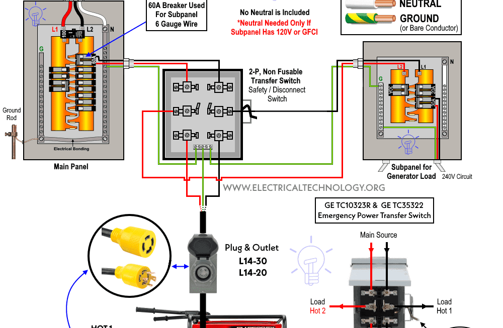
The main components of a Reliance transfer switch include the utility power input, generator input, load center terminals, and control wires. Each component plays a crucial role in ensuring that power is safely and efficiently transferred from the utility to the generator.
When the utility power goes out, the transfer switch detects the loss of power and automatically switches to the generator as the new power source. This seamless transition is made possible by the internal wiring diagram, which dictates how the switch operates in different scenarios.
It is important to follow the wiring diagram provided by the manufacturer when installing a Reliance transfer switch. Proper installation ensures that the switch functions correctly and minimizes the risk of electrical hazards. If you are unsure about the wiring process, it is always best to consult a professional electrician.
In conclusion, understanding the internal wiring diagram of a Reliance transfer switch is crucial for ensuring a reliable power supply during outages. By familiarizing yourself with the components and connections of the switch, you can be better prepared to handle power disruptions effectively. Remember to always prioritize safety when working with electrical components.
Download and Print Reliance Transfer Switch Internal Wiring Diagram Listed below