Have you ever wondered how single-phase motors work? Understanding the wiring diagram is essential for proper installation and maintenance. In this article, we will explore the basics of single-phase motor wiring diagrams and how they can help you get the job done right.
Single-phase motors are commonly used in a variety of applications, from household appliances to industrial machinery. The wiring diagram is like a roadmap that guides you through the installation process, ensuring that all connections are made correctly to avoid any issues down the line.

Related Post Wiring Diagram 3 Phase Motor
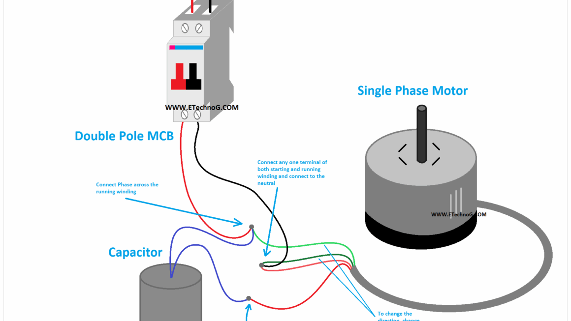
Single Phase Motor Wiring Diagram
When looking at a single-phase motor wiring diagram, you will see different components such as the starting capacitor, run capacitor, centrifugal switch, and winding connections. Each component plays a vital role in the motor’s operation, and understanding how they are connected is crucial for proper functioning.
The wiring diagram will typically show the proper connections for both the power supply and the motor terminals. It will also indicate which wires are for the starting circuit and which are for the running circuit. Following the diagram carefully will ensure that the motor operates efficiently and safely.
If you are unsure about how to read a single-phase motor wiring diagram, it is always best to consult a professional electrician. They have the knowledge and experience to help you decipher the diagram and make the necessary connections correctly. Taking the time to understand the wiring diagram will save you time and prevent any costly mistakes.
In conclusion, single-phase motor wiring diagrams are essential tools for anyone working with these types of motors. By following the diagram carefully and seeking help when needed, you can ensure that your motor operates smoothly and efficiently. Remember, safety always comes first when working with electrical components, so take the time to do the job right.
Download and Print Single Phase Motor Wiring Diagram Listed below