When it comes to installing a new thermostat for your heat pump, understanding the wiring diagram is crucial. Proper thermostat wiring ensures your heat pump functions efficiently and effectively.
Whether you’re a seasoned DIY enthusiast or a first-time homeowner, navigating the thermostat wiring for your heat pump can be a bit overwhelming. But don’t worry, we’re here to break it down for you!

Related Post 30 Amp Rv Power Converter Wiring Diagram
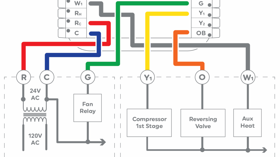
Next, identify the terminals on your heat pump and thermostat. Common terminals include R (power), C (common), Y (cooling), W (heating), and G (fan). Make sure to match the wires from your thermostat to the corresponding terminals on your heat pump.
If you’re unsure about the wiring configuration or have any doubts, don’t hesitate to seek professional help. Improper thermostat wiring can lead to system malfunctions and potential damage. It’s better to be safe than sorry when it comes to your heat pump’s performance.
Once you’ve successfully wired your thermostat to your heat pump, test the system to ensure everything is functioning correctly. Adjust the settings on your thermostat to activate heating and cooling modes, and listen for any unusual noises or issues.
In conclusion, understanding the thermostat wiring diagram for your heat pump is essential for optimal performance. By following the guidelines provided by your thermostat manufacturer and double-checking your wiring connections, you can ensure a smooth and efficient operation of your heat pump system.
So, the next time you’re tackling a thermostat installation for your heat pump, remember to refer to the wiring diagram, match the wires correctly, and test the system for proper functionality. With the right knowledge and attention to detail, you’ll be enjoying a comfortable home environment in no time!
Download and Print Thermostat Wiring Heat Pump Wiring Diagram Listed below