Are you looking to understand how a three-phase transformer works? You’ve come to the right place! In this article, we’ll delve into the intricacies of three-phase transformer wiring diagrams and break it down for you in simple terms.
Whether you’re an electrical enthusiast or a professional in the field, knowing how a three-phase transformer operates is essential. It plays a crucial role in distributing power efficiently and effectively in various industrial and commercial applications.

Related Post 2002 Chevy Silverado Radio Wiring Diagram
Three Phase Transformer Wiring Diagram
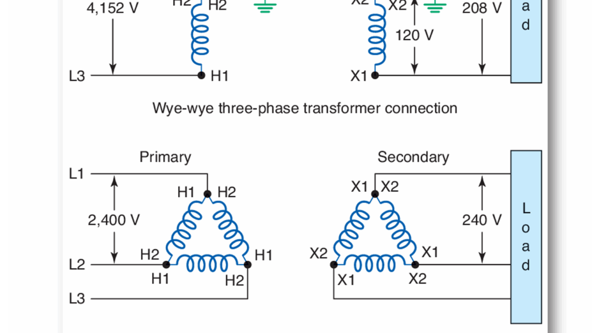
A three-phase transformer wiring diagram consists of three primary and three secondary windings. The primary windings are connected in a delta or wye configuration, while the secondary windings can also be delta or wye, depending on the application requirements.
Each of the three phases in a three-phase system is connected to a winding, and the magnetic flux generated in the primary windings induces a voltage in the secondary windings. This voltage is then distributed to the load, providing power for electrical equipment and machinery.
Understanding the phasor diagrams and connections in a three-phase transformer is crucial for ensuring proper operation and efficiency. Proper wiring and configuration are essential to prevent voltage imbalances and ensure the smooth functioning of the electrical system.
In conclusion, a three-phase transformer wiring diagram is a vital component in the distribution of power in industrial and commercial settings. By understanding the connections and configurations involved, you can ensure the safe and efficient operation of your electrical system.
Download and Print Three Phase Transformer Wiring Diagram Listed below