Are you having issues with your throttle position sensor and need a wiring diagram to help troubleshoot the problem? Look no further! Understanding the throttle position sensor wiring diagram is crucial for diagnosing and fixing any issues with your vehicle’s throttle system.
The throttle position sensor (TPS) is a vital component of your vehicle’s engine management system. It measures the position of the throttle valve and sends signals to the engine control unit (ECU) to adjust the air-fuel mixture for optimal performance. Without a properly functioning TPS, your vehicle may experience poor acceleration, stalling, or even difficulty starting.

Related Post Boat Marine Dual Battery Switch Wiring Diagram
If you’re experiencing problems with your vehicle’s throttle system, such as erratic idle, poor acceleration, or stalling, referencing the throttle position sensor wiring diagram can help you pinpoint the issue. Whether you’re a seasoned mechanic or a DIY enthusiast, having this information at your fingertips can save you time and money on repairs.
In conclusion, the throttle position sensor wiring diagram is a valuable tool for troubleshooting any issues with your vehicle’s throttle system. By understanding how the TPS functions and how it is connected to the ECU, you can effectively diagnose and fix any problems that may arise. So next time you’re facing issues with your throttle, don’t forget to consult the wiring diagram for guidance.
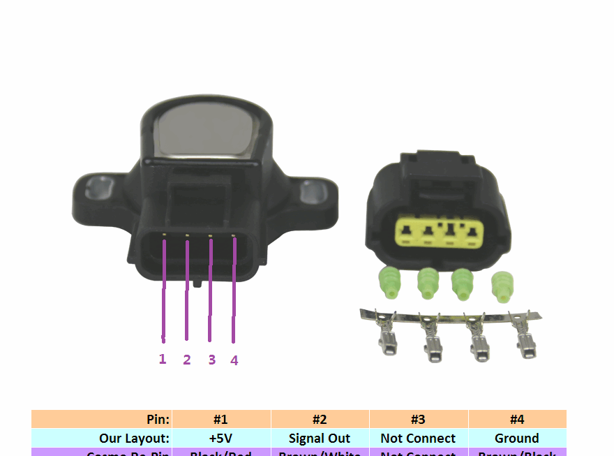
Download and Print Throttle Position Sensor Wiring Diagram Listed below