If you’re looking to install universal turn signals on your vehicle, having a wiring diagram can make the process much easier. Understanding how to properly wire your turn signals is crucial for safety on the road.
With a universal turn signal wiring diagram, you can easily identify the wires and connectors needed to complete the installation. This diagram will guide you through the process step by step, ensuring that everything is connected correctly.

Related Post 3 Phase Contactor Wiring Diagram
Next, locate the wiring harness under your vehicle’s dashboard. This is where you’ll connect the wires from the universal turn signal kit. Use the wiring diagram as a reference to ensure each wire is connected to the correct terminal.
Once all the wires are connected, test the turn signals to make sure they are functioning properly. You may need to troubleshoot any issues that arise, such as a flickering light or a non-responsive signal. The wiring diagram can help you identify and fix these problems.
After testing the turn signals, secure all the wires with electrical tape and tidy up the installation. Make sure everything is properly insulated to prevent any short circuits or electrical malfunctions while driving.
In conclusion, having a universal turn signal wiring diagram is essential for a successful installation. By following the diagram and taking your time to connect the wires correctly, you can ensure that your turn signals work effectively and keep you safe on the road.
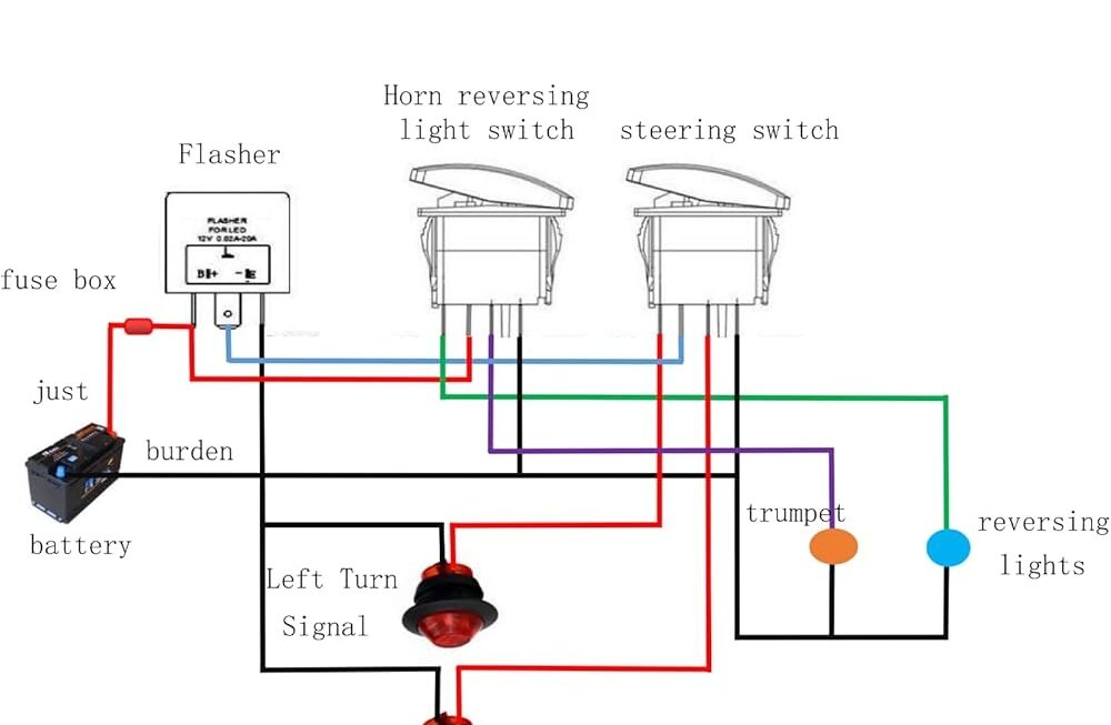
Download and Print Universal Turn Signal Wiring Diagram Listed below

Related Post Wiring Diagram For 5 Pin Rocker Switch