Are you looking to install a brake controller in your vehicle but feeling overwhelmed by the wiring process? Don’t worry, we’ve got you covered! In this article, we will provide you with a simple and easy-to-follow wiring diagram for a brake controller.
Having a brake controller is essential for towing a trailer safely. It ensures that your trailer’s brakes are synchronized with your vehicle’s brakes, allowing for smoother stops and better control while on the road.

Related Post Universal Headlight Switch Wiring Diagram
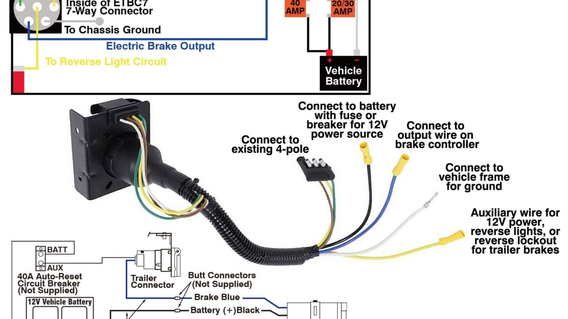
Next, you will need to connect the brake controller’s power wire to the positive terminal of the vehicle’s battery. This will ensure that the brake controller is receiving the necessary power to function properly.
After that, you will need to connect the brake controller’s ground wire to a solid grounding point on the vehicle. This will complete the circuit and allow the brake controller to function effectively.
Finally, you will need to connect the brake controller’s brake wire to the vehicle’s brake light switch. This will ensure that the brake controller activates the trailer’s brakes when you apply the brakes in your vehicle.
Once you have completed these steps, you can test the brake controller to ensure that it is working correctly. If everything is functioning as it should, you are now ready to hit the road with your trailer in tow!
With this easy-to-follow wiring diagram for a brake controller, you can install this essential piece of equipment in your vehicle with confidence. Now you can enjoy safe and smooth towing experiences without any worries. Happy towing!
Download and Print Wiring Diagram For Brake Controller Listed below