Are you looking to install an electric trailer brake controller but not sure where to start? Understanding the wiring diagram is key to a successful installation. Let’s break it down for you!
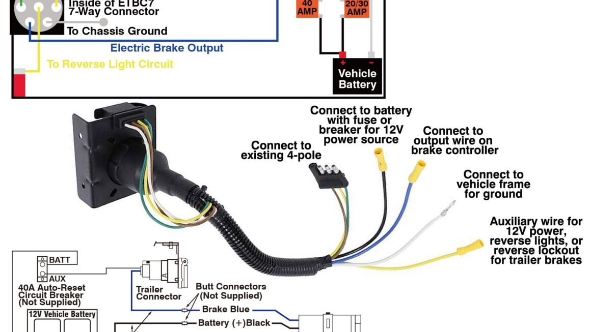
First and foremost, it’s important to familiarize yourself with the different components involved in the wiring diagram for an electric trailer brake controller. This includes the controller itself, the trailer connector, and the vehicle’s electrical system.

Related Post Universal Turn Signal Wiring Diagram
When installing the electric trailer brake controller, it’s crucial to follow the manufacturer’s instructions carefully. This will help prevent any wiring errors that could potentially lead to malfunctioning brakes or other safety hazards while towing.
Additionally, make sure to use the appropriate gauge of wire for the installation to ensure proper conductivity and avoid any overheating issues. It’s always better to err on the side of caution when it comes to electrical connections.
Lastly, don’t hesitate to seek help from a professional if you’re unsure about any aspect of the wiring diagram or installation process. Safety should always be the top priority when it comes to towing, so it’s better to have the job done right the first time.
In conclusion, understanding the wiring diagram for an electric trailer brake controller is essential for a safe and successful installation. By following the manufacturer’s instructions, using the correct wiring components, and seeking help when needed, you can ensure that your trailer brakes are working effectively when you hit the road.
Download and Print Wiring Diagram For Electric Trailer Brake Controller Listed below