If you’re looking to understand how a pressure switch works in your home or business, you’ve come to the right place. In this article, we’ll break down the wiring diagram for a pressure switch in a way that’s easy to understand.
Pressure switches are commonly used in various applications to monitor and control the pressure of liquids or gases. They play a crucial role in ensuring that systems operate efficiently and safely. Understanding the wiring diagram for a pressure switch is essential for proper installation and troubleshooting.

Related Post Pioneer Dmh-1770Nex Wiring Diagram
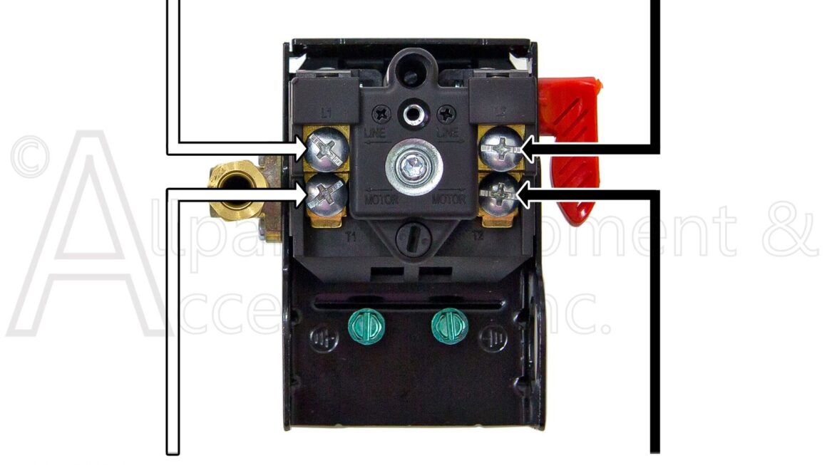
When wiring a pressure switch, it’s essential to follow the manufacturer’s instructions carefully. Typically, a pressure switch will have terminals for power, ground, and the load (such as a pump or motor). It’s crucial to connect the wires correctly to ensure the switch functions properly.
In the wiring diagram for a pressure switch, you’ll typically see a schematic that shows the connections between the various components. It’s important to pay attention to the wiring color codes and terminal labels to ensure a correct and safe installation. If you’re unsure about any part of the diagram, don’t hesitate to seek help from a professional.
Properly wiring a pressure switch is crucial for the efficient operation of your system and the safety of those around it. By understanding the wiring diagram and following the manufacturer’s guidelines, you can ensure that your pressure switch functions as intended.
In conclusion, understanding the wiring diagram for a pressure switch is essential for anyone working with these devices. By following the proper procedures and guidelines, you can ensure a safe and efficient operation of your system. If you have any questions or need further assistance, don’t hesitate to reach out to a professional for help.
Download and Print Wiring Diagram For Pressure Switch Listed below