If you’ve ever wondered how a shunt trip circuit breaker works, you’re in the right place! In this article, we’ll discuss the wiring diagram for a shunt trip circuit breaker and how it functions.
A shunt trip circuit breaker is a type of circuit breaker that includes an electromagnetic coil that can be remotely tripped to open the circuit. This is often used in industrial settings where safety is a top priority.

Related Post 7-Pin Trailer Plug Wiring Diagram With Brakes
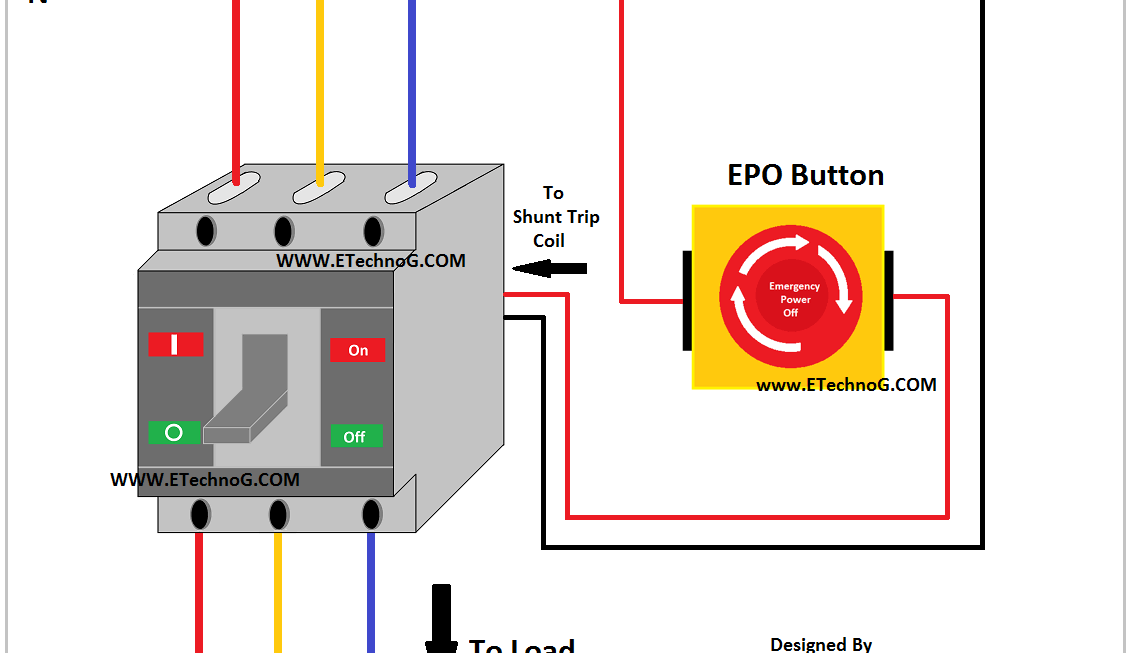
One key component in the wiring diagram is the shunt trip coil, which is connected in parallel with the circuit. When activated, this coil creates a magnetic field that trips the breaker, opening the circuit and shutting off the power.
Another important part of the wiring diagram is the control circuit, which includes a switch or button that can be used to trigger the shunt trip coil. This allows for manual activation of the shunt trip feature when needed.
It’s crucial to follow the manufacturer’s instructions when wiring a shunt trip circuit breaker to ensure proper functionality and safety. Incorrect wiring can result in the breaker not tripping when necessary, putting individuals and equipment at risk.
In conclusion, understanding the wiring diagram for a shunt trip circuit breaker is essential for ensuring the safety and proper operation of electrical systems. By following the correct wiring procedures and components, you can effectively incorporate this important safety feature into your industrial or commercial applications.
Download and Print Wiring Diagram For Shunt Trip Circuit Breaker Listed below