Looking to install a 120 volt well pump pressure switch and need a wiring diagram to guide you through the process? You’ve come to the right place! In this article, we’ll walk you through the steps to wire your pressure switch correctly.
Before we dive into the wiring diagram, let’s first understand the basics. A pressure switch is a device that monitors the water pressure in your well system and controls the operation of the pump. It ensures that the pump turns on and off at the correct pressure levels, preventing damage and ensuring efficient operation.

Related Post 2000 Chevy Silverado Ignition Switch Wiring Diagram
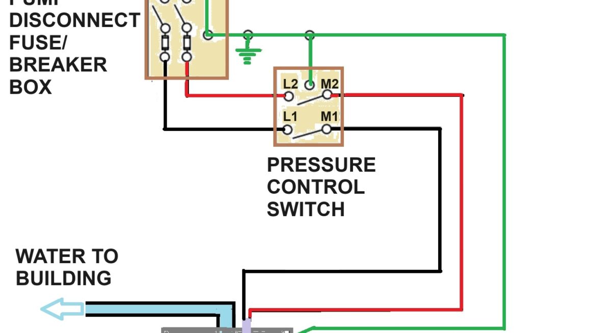
Next, connect the power supply wires to the corresponding terminals on the pressure switch, usually labeled L1 and L2. Then, connect the pump motor wires to the terminals marked T1 and T2. Double-check all connections to ensure they are secure and properly insulated.
Once you’ve completed the wiring, turn the power back on and test the system to ensure everything is working correctly. Monitor the pressure levels and listen for the pump to turn on and off at the appropriate times. If you encounter any issues, refer back to the wiring diagram and troubleshoot as needed.
In conclusion, wiring a 120 volt well pump pressure switch is a straightforward process when following the manufacturer’s instructions and using a wiring diagram as a guide. By ensuring all connections are secure and correctly made, you can have your well system up and running smoothly in no time.
Now that you have a better understanding of how to wire a 120 volt well pump pressure switch, you can tackle the installation with confidence. Remember to always prioritize safety and follow the guidelines provided to ensure a successful and efficient well system. Happy wiring!
Download and Print 120 Volt Well Pump Pressure Switch Wiring Diagram Listed below