Have you ever wondered how a 3 wire RTD wiring diagram works? RTD, or Resistance Temperature Detector, is a sensor used to measure temperature by correlating the resistance of the RTD element with temperature. In this article, we will explore the wiring diagram for a 3 wire RTD.
Understanding the wiring diagram for a 3 wire RTD is essential for accurate temperature measurement. The 3 wire configuration helps compensate for lead wire resistance, ensuring more accurate results. Let’s dive into the details of how to wire a 3 wire RTD sensor.

Related Post Wiring Diagram For 1965 Vw Type 1 Bug
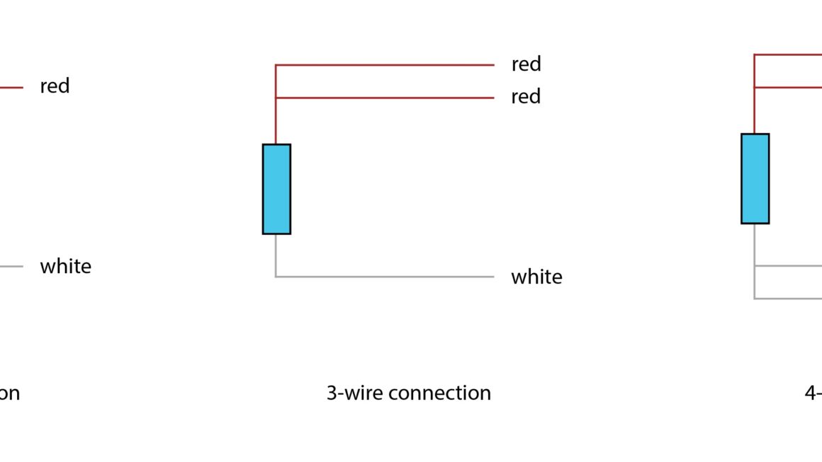
3 Wire RTD Wiring Diagram
In a 3 wire RTD configuration, there are three wires: one is the sensing element, and the other two are used for lead wire compensation. The sensing element is connected to the measurement device, while the two lead wires are connected to a Wheatstone bridge circuit.
The Wheatstone bridge circuit is used to measure the resistance of the RTD element accurately. By comparing the resistance of the RTD element with the reference resistors in the Wheatstone bridge, the temperature can be accurately calculated. This configuration helps eliminate errors caused by lead wire resistance.
When wiring a 3 wire RTD, it is crucial to ensure that the connections are made correctly to avoid measurement errors. The wiring diagram for a 3 wire RTD typically shows the connections for the sensing element and the lead wires to the measurement device. Following the diagram accurately is key to obtaining precise temperature measurements.
In conclusion, understanding the wiring diagram for a 3 wire RTD is essential for accurate temperature measurement. By following the correct wiring configuration and using a Wheatstone bridge circuit, you can ensure precise and reliable temperature readings. So next time you work with a 3 wire RTD sensor, refer to the wiring diagram to get the best results.
Download and Print 3 Wire Rtd Wiring Diagram Listed below