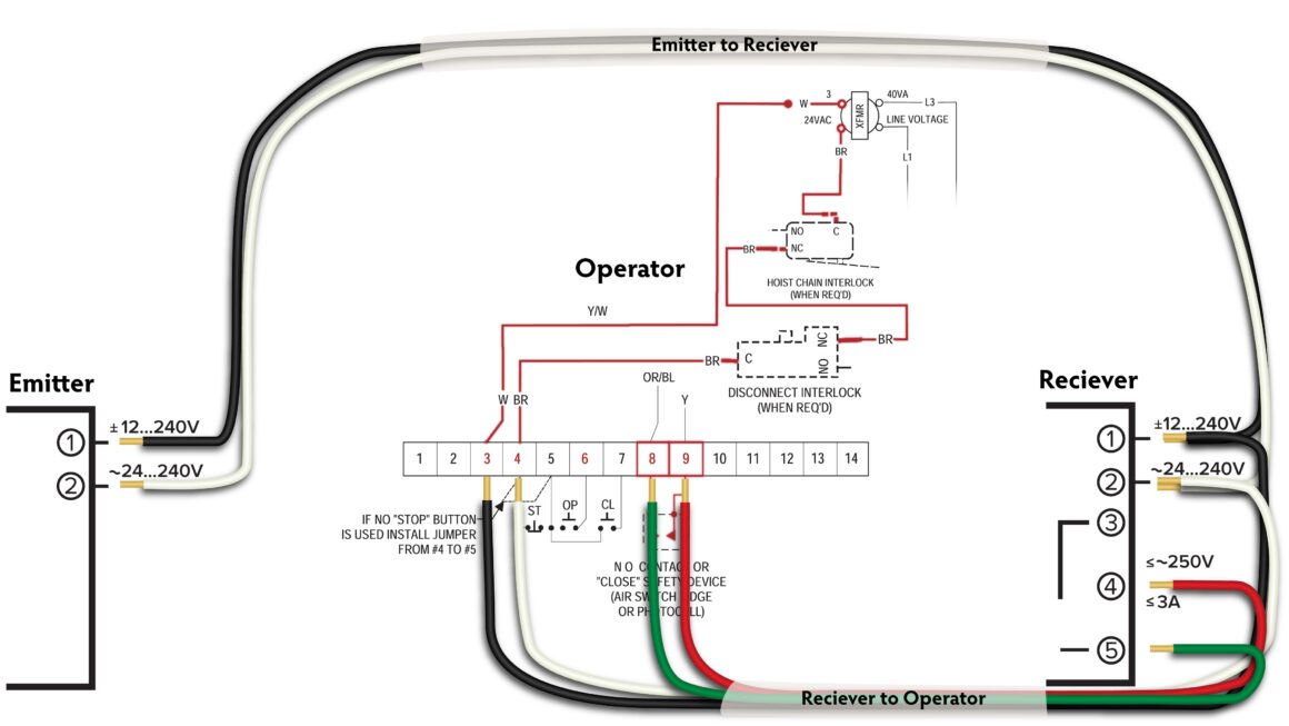
If you’re looking to install or troubleshoot your Liftmaster garage door sensor, understanding the wiring diagram is essential. This diagram will guide you on how to properly connect the sensors to ensure your garage door operates smoothly and safely.
By following the Liftmaster garage door sensor wiring diagram, you can easily identify which wires connect to the sensor’s power source, motor, and control panel. This will help you avoid any confusion and ensure that your garage door functions properly.

Related Post Electric Hot Water Heater Wiring Diagram
It’s important to carefully follow the wiring diagram provided by Liftmaster to ensure that the sensors are properly connected. Incorrect wiring can lead to malfunctioning sensors, which can compromise the safety and security of your garage door.
If you’re unsure about how to interpret the wiring diagram or how to properly connect the sensors, it’s best to consult a professional garage door technician. They have the knowledge and expertise to ensure that the sensors are installed correctly and that your garage door operates smoothly.
By understanding the Liftmaster garage door sensor wiring diagram and following it diligently, you can ensure that your garage door functions properly and safely. Proper installation and maintenance of the sensors are crucial for the overall performance and longevity of your garage door system.
So, next time you’re installing or troubleshooting your Liftmaster garage door sensor, refer to the wiring diagram provided by the manufacturer. This simple yet crucial step can make a significant difference in the functionality and safety of your garage door.
Download and Print Liftmaster Garage Door Sensor Wiring Diagram Listed below