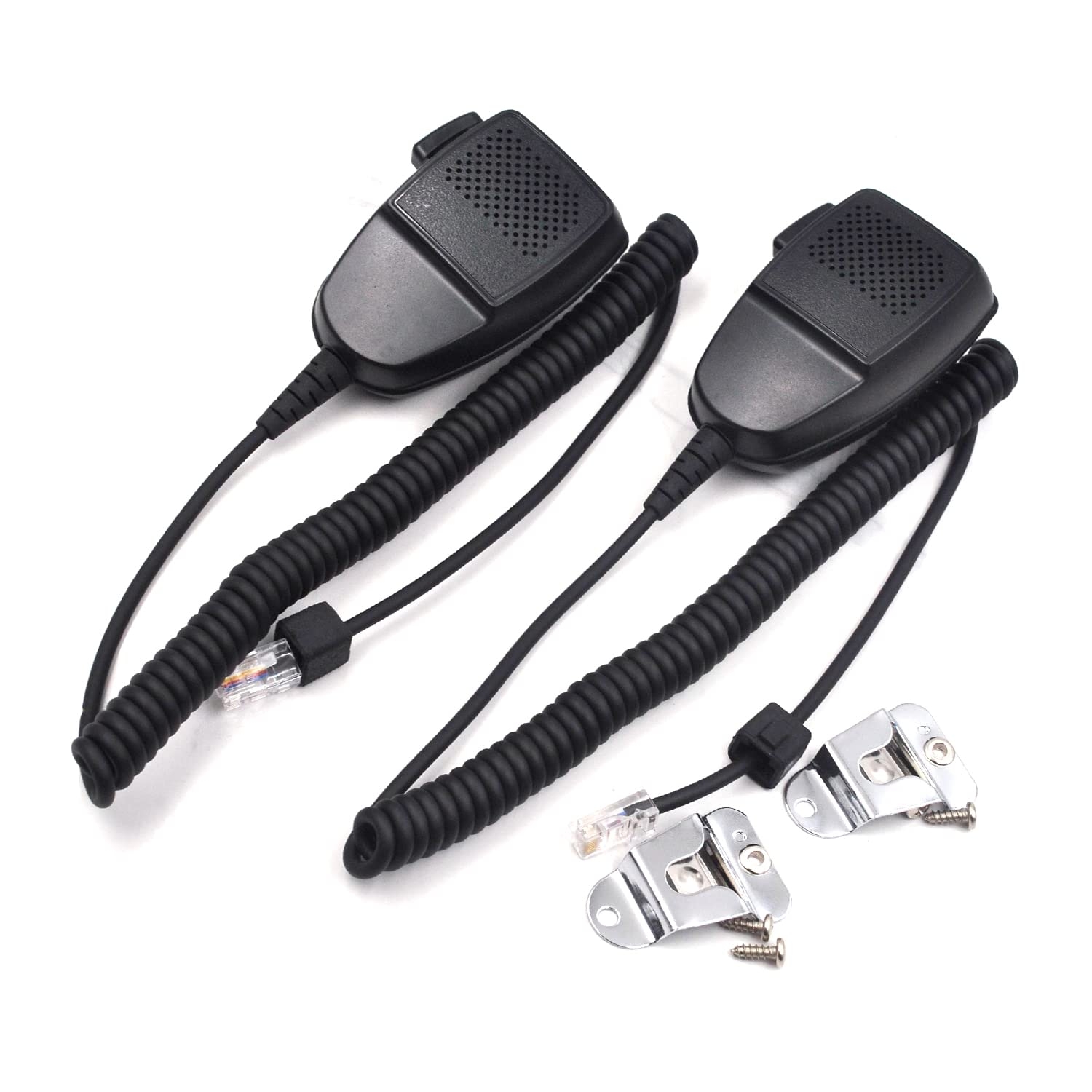
If you’re looking to set up your CB radio with an RJ45 microphone, you may be wondering how to wire it correctly. Understanding the RJ45 CB mic wiring diagram is essential for proper functionality.
Having the right wiring setup ensures that your microphone connects seamlessly to your CB radio, allowing you to communicate clearly without any issues.
Related Post 6 Prong Trailer Wiring Diagram
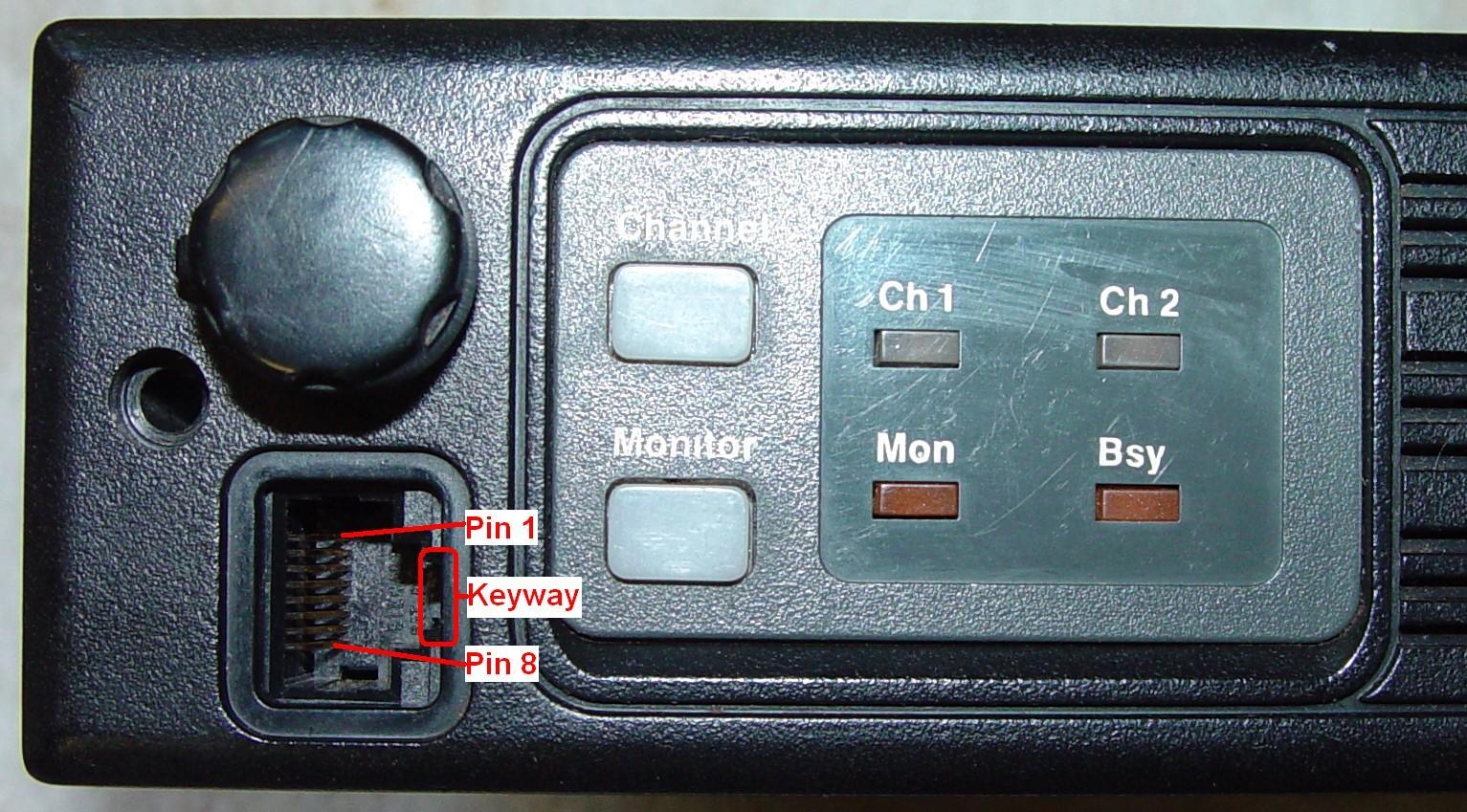
Firstly, you’ll need to identify the pinout of your RJ45 connector. This will determine which wires correspond to the microphone’s functions, such as audio, ground, and push-to-talk (PTT).
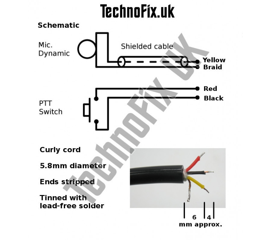
Typically, the wiring diagram will outline which wire corresponds to each function, making it easier for you to connect the microphone correctly. Following the diagram step by step will ensure that your microphone functions properly with your CB radio.
Once you’ve wired your RJ45 microphone according to the diagram, you can test it out to ensure everything is working correctly. Testing the microphone will allow you to make any necessary adjustments before regular use.
In conclusion, understanding the RJ45 CB mic wiring diagram is crucial for setting up your CB radio system correctly. By following the diagram and connecting the wires accordingly, you can ensure seamless communication while using your microphone with your CB radio.
Download and Print Rj45 Cb Mic Wiring Diagram Listed below
