Have you ever wondered how shunt trip circuit breakers work? Understanding the wiring diagram is crucial for ensuring safety and efficiency in your electrical system.
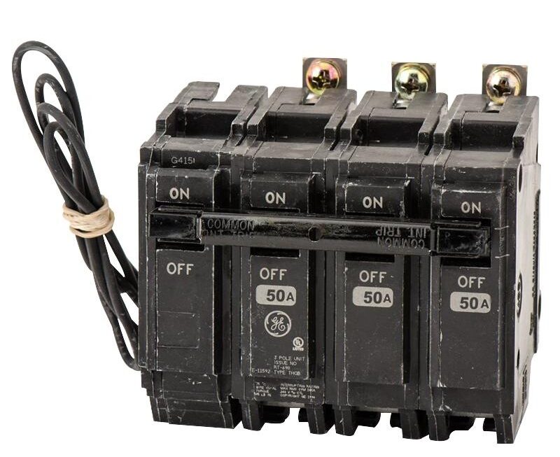
Shunt trip circuit breakers are designed to trip when a specific condition occurs, such as a fire alarm being activated. This added functionality can be a lifesaver in emergency situations.

Related Post Wiring Diagram Generator Transfer Switch
Typically, the wiring diagram will include the connections for the shunt trip coil, the auxiliary contacts, and the main circuit. Each component plays a crucial role in the overall functionality of the circuit breaker.
It’s essential to use the correct gauge of wire and ensure that all connections are secure to prevent any potential hazards. If you’re unsure about any aspect of the wiring diagram, it’s best to consult a professional electrician for guidance.
By understanding the shunt trip circuit breaker wiring diagram, you can ensure that your electrical system is operating safely and efficiently. Taking the time to familiarize yourself with the diagram can help you troubleshoot any issues that may arise in the future.
Remember, safety should always be your top priority when working with electrical systems. By following the correct wiring diagram and best practices, you can help prevent accidents and ensure the longevity of your equipment.
Next time you’re working with a shunt trip circuit breaker, take a moment to review the wiring diagram. It may seem complex at first, but with practice, you’ll become more comfortable navigating the connections and understanding how everything fits together.