If you’re looking to understand how to wire a single-phase reversible motor, you’ve come to the right place. In this article, we’ll break down the process in a simple and easy-to-follow manner.
Whether you’re a DIY enthusiast or a professional electrician, knowing how to wire a single-phase reversible motor is an essential skill. With the right knowledge and tools, you can easily get the job done.

Related Post 12 Volt Fuel Gauge Wiring Diagram For Boat
Start by identifying the starting winding and running winding terminals on the motor. Connect one end of the starting winding to one of the main terminals and the other end to one of the additional terminals. Repeat this process for the running winding, connecting it to the remaining main and additional terminals.
Once the windings are connected, you’ll need to wire the motor for forward and reverse operation. To achieve forward rotation, connect the main and additional terminals as described in the motor’s wiring diagram. For reverse rotation, simply swap the connections of the additional terminals.
After completing the wiring process, double-check all connections to ensure they are secure and properly insulated. Test the motor by applying power and verifying that it rotates in both forward and reverse directions. If everything is working correctly, you’re all set!
In conclusion, wiring a single-phase reversible motor may seem daunting at first, but with the right guidance, it can be a straightforward task. By following the steps outlined in this article and referencing the motor’s wiring diagram, you’ll be able to wire your motor with confidence.
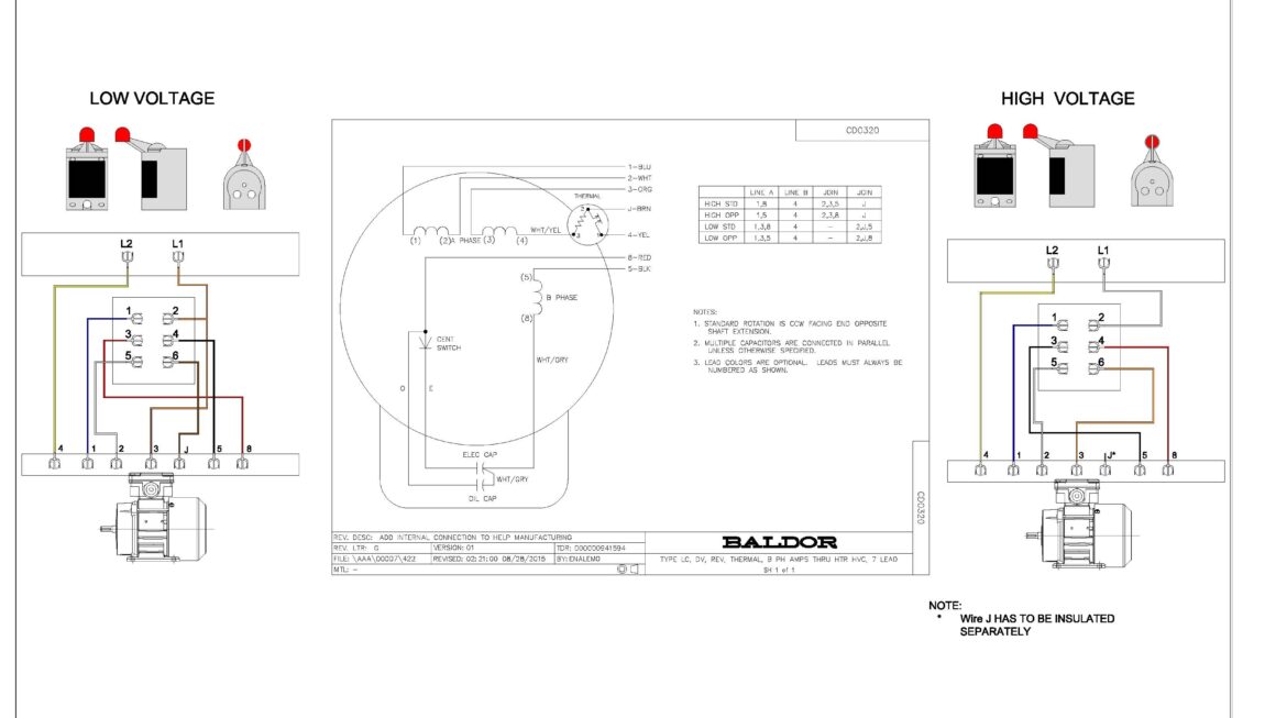
Download and Print Single Phase Reversible Motor Wiring Diagram Listed below