If you’re looking to install a trailer brake controller in your vehicle, understanding the wiring diagram is crucial. This diagram will help you connect the controller properly for safe towing.
Trailer brake controller wiring diagrams can vary depending on the make and model of your vehicle. It’s important to follow the specific diagram provided by the manufacturer to ensure proper installation.

Related Post Wiring Diagram For Switch Outlet Combo
Before starting the installation process, make sure to disconnect the negative battery cable to prevent any electrical mishaps. It’s also a good idea to consult your vehicle’s owner’s manual for any specific instructions or precautions.
Once you have the wiring diagram and necessary tools ready, you can begin connecting the wires according to the diagram. Take your time and double-check each connection to ensure everything is secure and properly attached.
After all the wires are connected, test the trailer brake controller to make sure it’s functioning correctly. You can do this by applying the brakes in your vehicle and checking if the trailer brakes engage smoothly.
In conclusion, understanding the trailer brake controller wiring diagram is essential for a successful installation. By following the diagram provided by the manufacturer and taking necessary precautions, you can safely connect the controller and enjoy worry-free towing experiences.
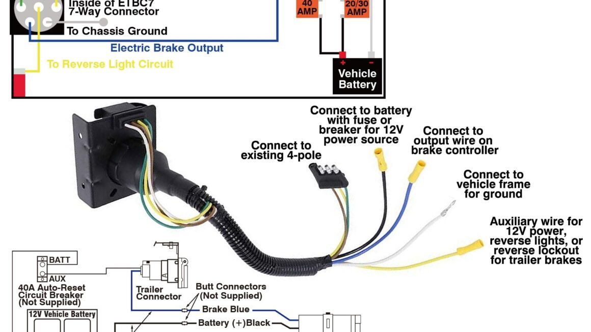
Download and Print Trailer Brake Controller Wiring Diagram Listed below

Related Post Liftmaster Garage Door Sensor Wiring Diagram